 Charles Ahrens
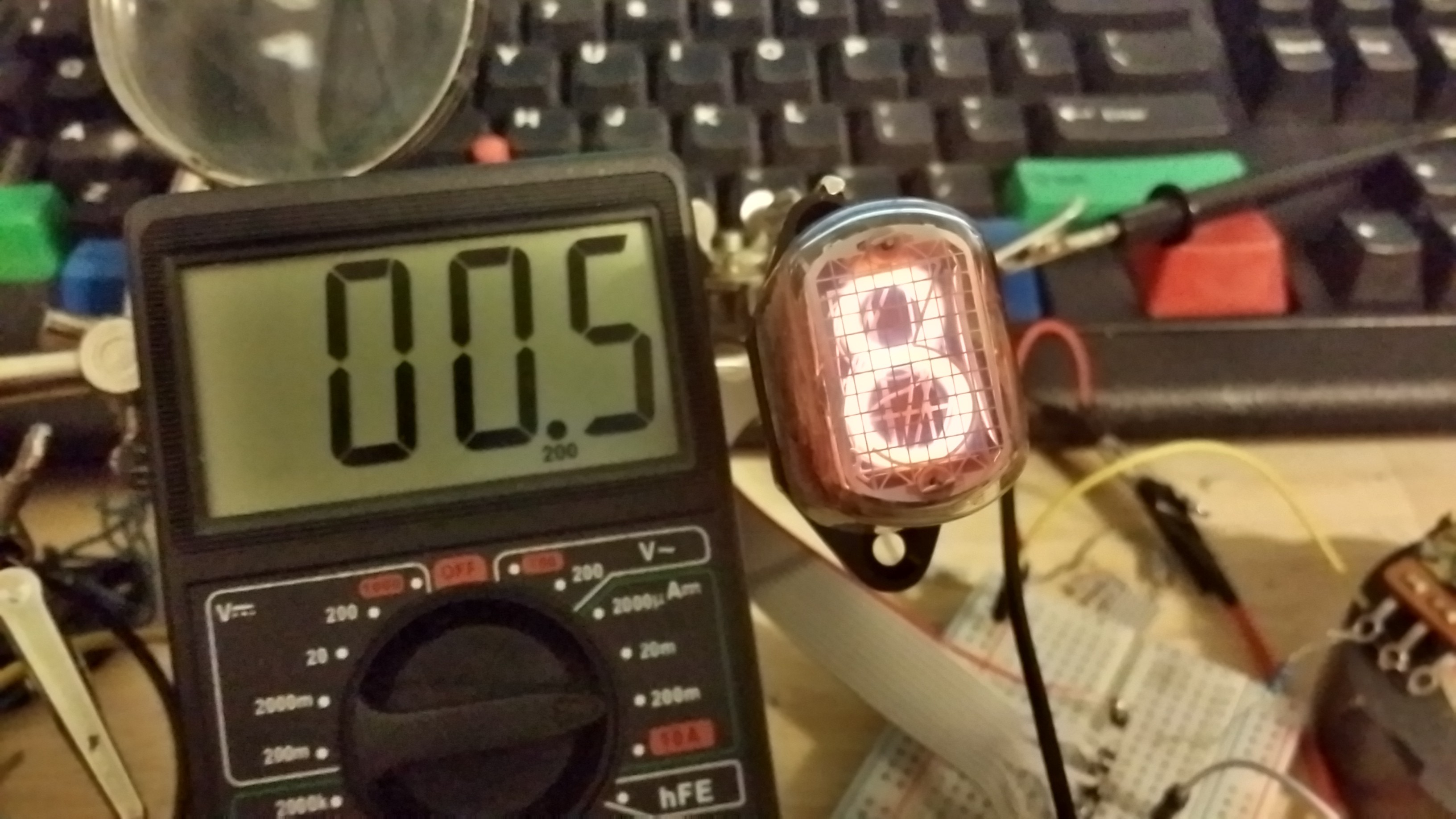
I wired up a connector from the IN-12 Nixie socket to breadboard header pins, with the pins in order for the digits on the tube. The high voltage anode was kept separate so that I didn't accidentally short anything while testing. I then tried to calculate the correct value of the anode resistor for the tube. I started with a supply at 180v and a 10k ohm resistor, but the current in the tube was just at the maximum value, around 3.6 mA, so I used a 100k ohm potentiometer to determine the perfect value. I started dimming the potentiometer until I reached a good brightness. 3.6 mA was too bright and I was worried about the tube, whereas 0.5 mA was too dark, and the number started getting fuzzy. Around 2.0 mA, the brightness was just right, and the number was crisp and readable. I measured the resistance and determined that a value of around 20k ohm would produce about 2.0 mA across the tube (or 2.2 mA with the decimal point and number lit).


Discussions
Become a Hackaday.io Member
Create an account to leave a comment. Already have an account? Log In.