 Charles Ahrens
I used the electronics lab facilities (and software) at my college to simulate the anode switching circuit for the tubes, and it seems to be working. The power dissipated through the MPSA92 is a little worrying, though, since the simulation software says that it will draw about 3.8W, when the datasheet says that the maximum rating for that transistor is 1.5W.
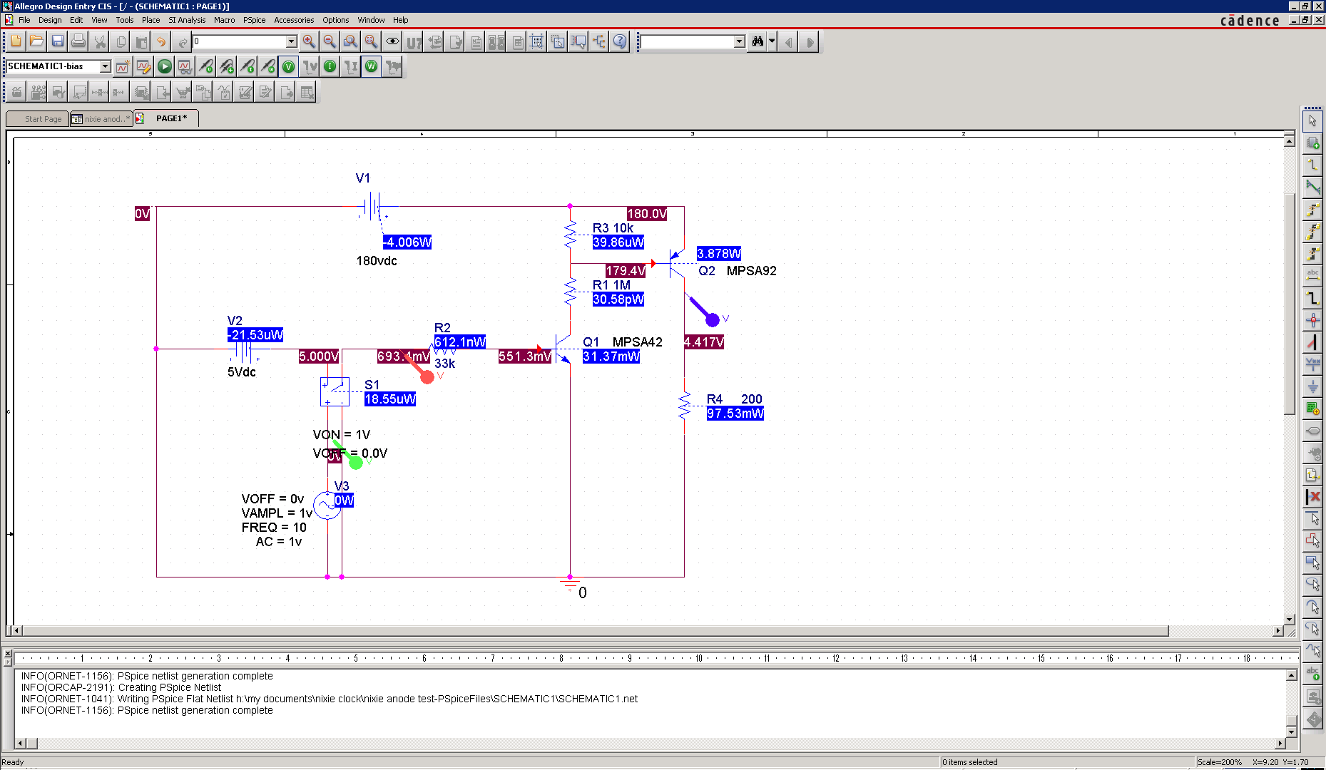
When I have tested this circuit before on the breadboard, the MPSA92 (or the '42) get really really warm (and sometimes burn out) while the tube remains lit regardless of the input voltage on the MPSA42. According to the simulation, this circuit with these resistance values and the voltage lines connected as shown should work to switch the anodes for each tube on. I will test this on a breadboard when I next get a chance, but if it doesn't work, I will just resort to the tried and true method of using 74141 chips to switch the cathodes instead of the discrete transistors and leaving the anodes of each tube set to 180V.
Discussions
Become a Hackaday.io Member
Create an account to leave a comment. Already have an account? Log In.