 Antti Lukats
Step 1
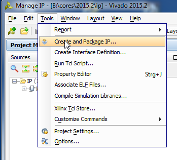
Start Vivado, Click on Icon Tasks, Manage IP

Select either New IP Location or Open IP Location if you have already made some IP Cores
Step 2
Step 3
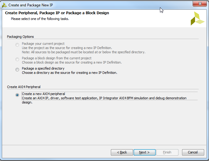
Select AXI Peripheral
Step 4
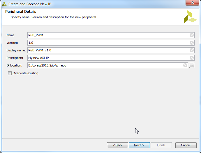
Pickup some name
Step 5
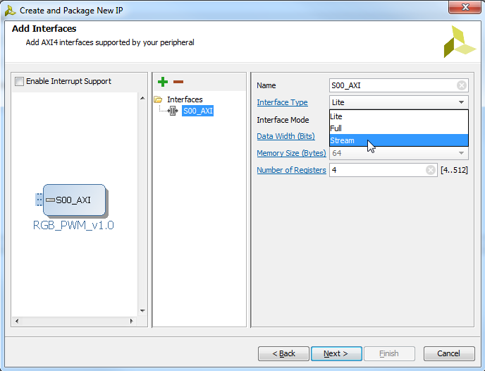
Sekect Stream, next and finish
Step 6

Edit in IP Packager
Step 7
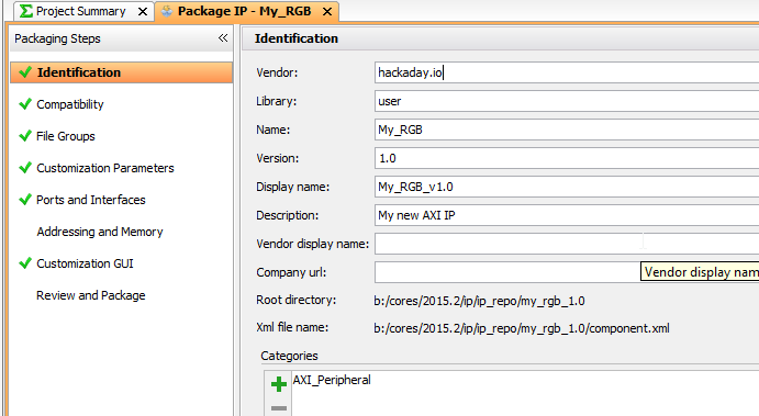
Pickup some "vendor" VLNV to your liking, like hackaday.io !
Step 8

Remove the wizard generated AXI Stream "dummy" from the IP Core project
Step 9
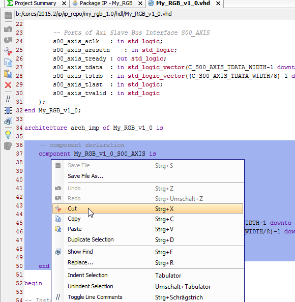
Remove the component declaration (to the file we just removed from project)
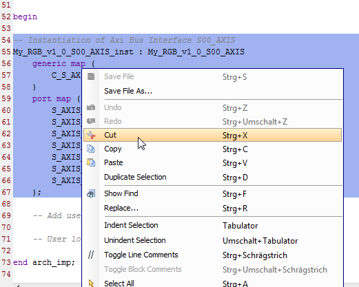
Remove the component instantion as well
Step 10
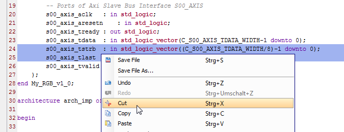
Delete TSTRB and TLAST ports we do not need them
STEP 11
Copy paste s00_axis_ready and add: <= '1'
s00_axis_tready <= '1';With this we tell that we are ALWAYS ready.Step 12
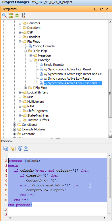
Select Templates, and copy the template body in the IP main body, and replace using copy paste
<clock> with s00_axis_aclk
<reset> with s00_axis_aresetn
<clock_enable> with s00_axis_tvalid
process (s00_axis_aclk)
begin
   if s00_axis_aclk'event and s00_axis_aclk='1' then
      if s00_axis_aresetn='0' then
         <output> <= '0';
      elsif s00_axis_tvalid ='1' then
         <output> <= <input>;
      end if;
   end if;
end process;
Like this, now we have created a Latch that samples data sent to us, data that we want to use for RGB LED PWM Control.Step 13
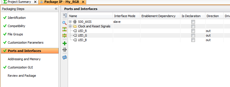
We could have done it earlier, but lets do it now, we use some copy paste again, to get one Output to our IP Core

We copy and paste this, and change it to say LED_R, then make the same for G and B too
		-- Users to add ports here
        LED_R	: out std_logic;
        LED_G	: out std_logic;
        LED_B	: out std_logic;
		-- User ports ends
like thisStep 14
Now we should implement the PWM control, but for testing we make on off control only, then we can later add the PWM.
Let say we would like to use 8 bit PWM later, so we have a byte for each color, for on-off control we use the MSB bits.
So we send D7 to Blue, D15 to Green, and D23 to Red LED, first some copy and paste again, to have code like this
process (s00_axis_aclk)
begin
   if s00_axis_aclk'event and s00_axis_aclk='1' then
      if s00_axis_aresetn='0' then
          LED_R <= '0';
          LED_G <= '0';
          LED_B <= '0';
      elsif s00_axis_tvalid ='1' then
         LED_R <= <input>;
         LED_G <= <input>;
         LED_B <= <input>;
      end if;
   end if;
end process;
the first 3 assignment assign the default RESET value of 0 to the RGB LED outputs. More copy paste, and we need to type the brackets and numbers!architecture arch_imp of My_RGB_v1_0 is
begin
s00_axis_tready <= '1';
process (s00_axis_aclk)
begin
if s00_axis_aclk'event and s00_axis_aclk='1' then
if s00_axis_aresetn='0' then
LED_R <= '0';
LED_G <= '0';
LED_B <= '0';
elsif s00_axis_tvalid ='1' then
LED_R <= s00_axis_tdata(23);
LED_G <= s00_axis_tdata(15);
LED_B <= s00_axis_tdata(7);
end if;
end if;
end process;
end arch_imp;We are done here. No more code is needed. Do not forget to save the file..Step 15
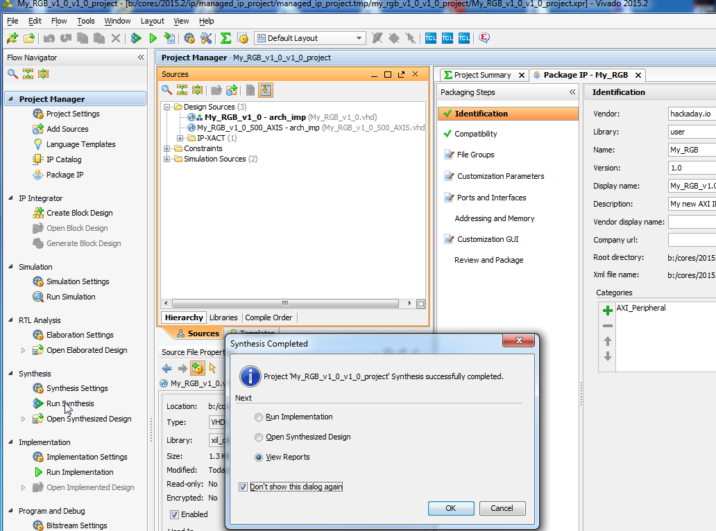
Click on Synthesis > Run Synthesis to check that it is all OK
Step 16
At the right there are items marked red, click on them and say each time MERGE :) until all turns green!
Step 17
Select Review and Package, and click on Package IP
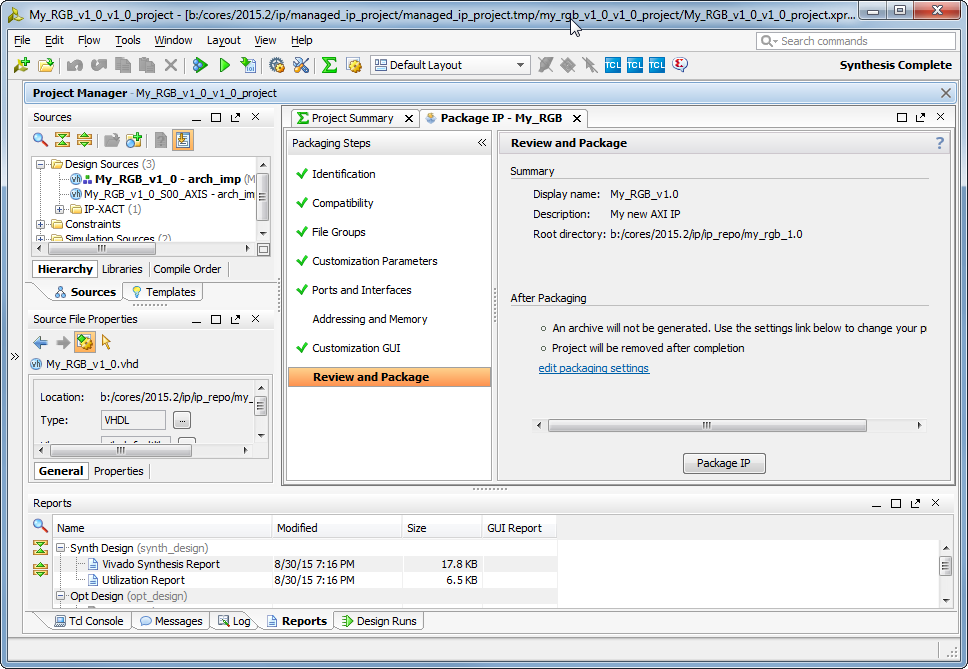
Choose "Close Project". We are Done, the IP Core is READY to be used in Vivado IP Core Catalog.
Next short walk-though how to use it.
Step 18
Create a new Vivado Project, select any part (or any part that your license does allow), next next just to get some project created and opened. Click on IP Integrator > Create Block Design, OK
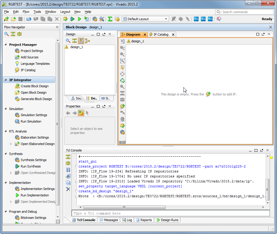
Do no click on the + Button yet, we need to tell Vivado where is our IP Core Catalog..
IP Catalog, select Add Repository choose the place where you created the RGB IP Core!
Now click on the + button to add IP, type rgb in search box, and doubleclick
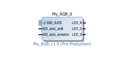
Our IP is now inserted into new SoC design!
Step 19
We need a Processor, preferable a free one, so Ctrl+I or right mouse-click, and start typing "micro.." and doublick on MicroBlaze

Then click on "Run Block Automation" and make selections as shown:
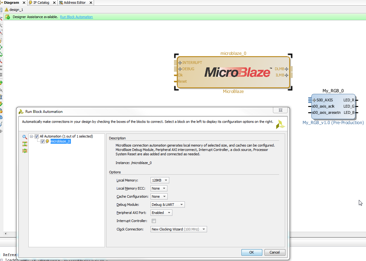
And click OK
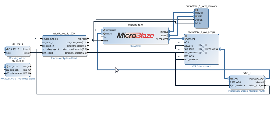
We have now RGB IP Core and full 32bit Risc based SoC including RAM and JTAG debug and virtual JTAG UART Console
Step 20
We need to interface our IP Core to the Processor, so we double click on MicroBlaze, select Advanced, buses and change the number of Stream Links from 0 to 1
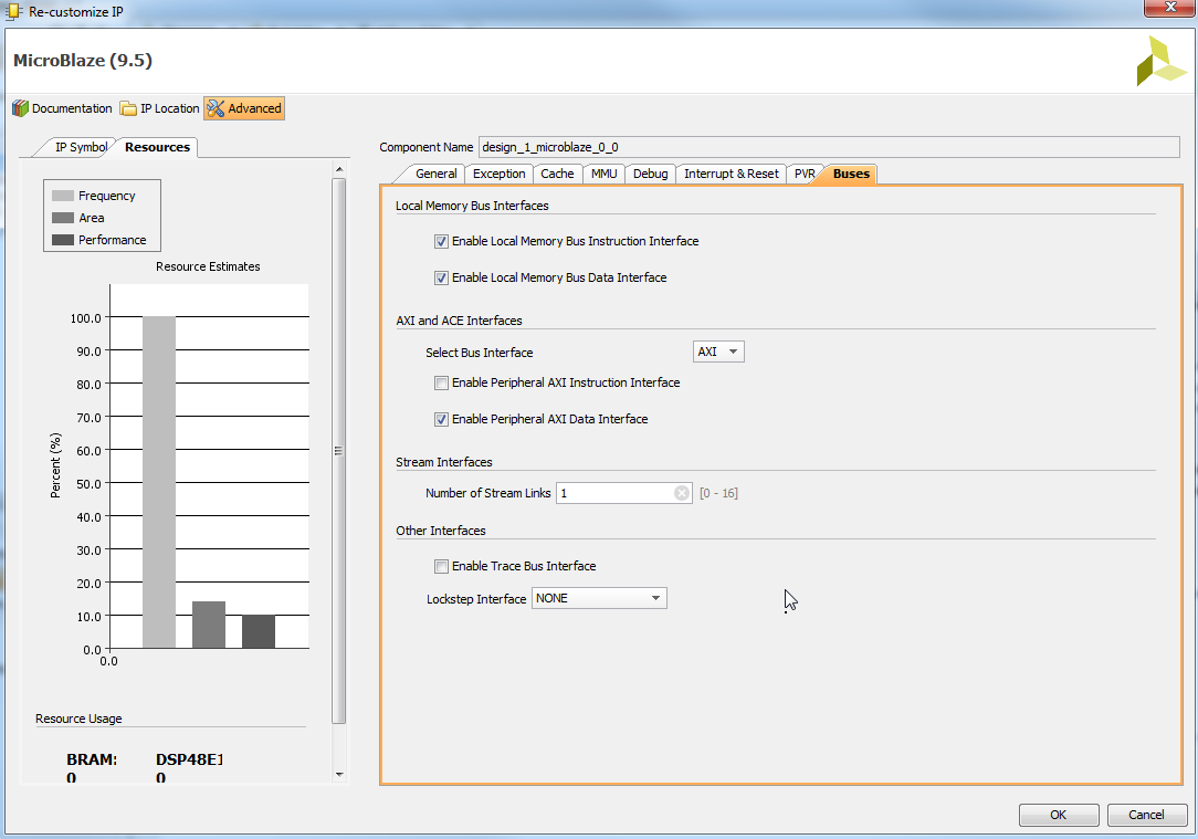
Click OK
Now we are ready to connect RGB IP to the Processor, use mouse drag like this..
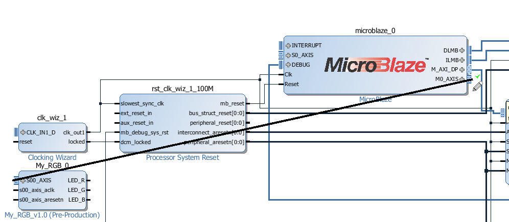
clock and reset lines need to be connected manually (there is a reason for this..)
Now we have to connect the RGB signals from the Processor to the real LED's right? Right click and choose "Make external" three times..
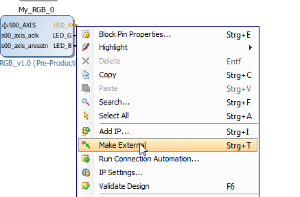
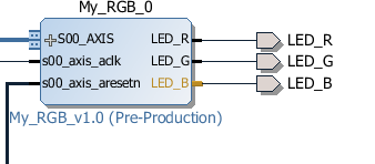
We are almost done.
I Skip some steps here..
Step 21
In Xilinx SDK we write
#include "fsl.h"This will include API for the special instructions to work with AXI4-Streams as if they would be custom CPU instructions.void SetRGB(u8 RED, u8 GREEN, u8 BLUE) { putfsl(RED <<16 | GREEN << 8 | BLUE, 0); }Now we define a function to control our IP Core
int main()
{
    print("Hello Hackaday\n\r");
    SetRGB(128, 128, 128); // make all ON
    while (1);
}
Thats all folks.We did create our IP Core, added it to SoC system, and we have C code that talks to it. We are ready to debug the Software on the Hardware we designed in the steps earlier.
The skipped steps are mostly click click and boring, will be explained later in details, in this LOG the main topic was creating the IP Core what is included with all steps as required.
Discussions
Become a Hackaday.io Member
Create an account to leave a comment. Already have an account? Log In.
Ubuntu users who don't have en_US locales set:
http://forums.xilinx.com/t5/Design-Entry/Vivado-2013-4-ERROR-IP-Flow-19-395-Problem-validating-against/td-p/416597
Step 19 failed for me because I had other locales set. Vivado then generates an error message that totally doesn't point towards this.
Are you sure? yes | no