 John
JohnThe WeMo (R) Insight is a "smart plug" that allows you to monitor a particular appliance and switch it on and off over WiFi. Check out Belkin's Description for more details. Out of the box you can only talk to it with the provided app or a few third party tools like IFTT. Some people have tried software hacks to control this device, one of the best is Ouimeaux. After looking into these tools for a while I decided they were still too limiting. Additionally I had serious problems getting the devices on my wireless network and keeping them connected. A hardware fix was needed!
At first I was hoping a simple antenna replacement would solve the WiFi issues. Following the guide here, I switched out the stock PCB antenna with a custom "high gain" one. I never quantified the RF quality of either antenna but in a few tests the WeMo reported better reception. In general though, the wireless problems were still present. Most likely the antenna was not the problem...
Time to crack the case open! After a few failed attempts and too much dremeling, I found the secret 3 triangular screws under the back sticker that keep the case together (see project instructions for photos). It turns out the device is composed of two separate PCB's. The high voltage components and solid state meter are on a "host board" and all of the smarts on a "control board". It was easy enough to attach some probes to the connector cable and figure out how the two communicated. ***DON'T TRY THIS WITHOUT THE RIGHT SAFETY EQUIPMENT*** So you don't have to mess with mains voltage, here's the connector pinout:
1: 3.3V Pull Up
2: UART TX (from solid state meter)
3: NC
4: GND
5: +5V
6: +5V
7: GND
8: Relay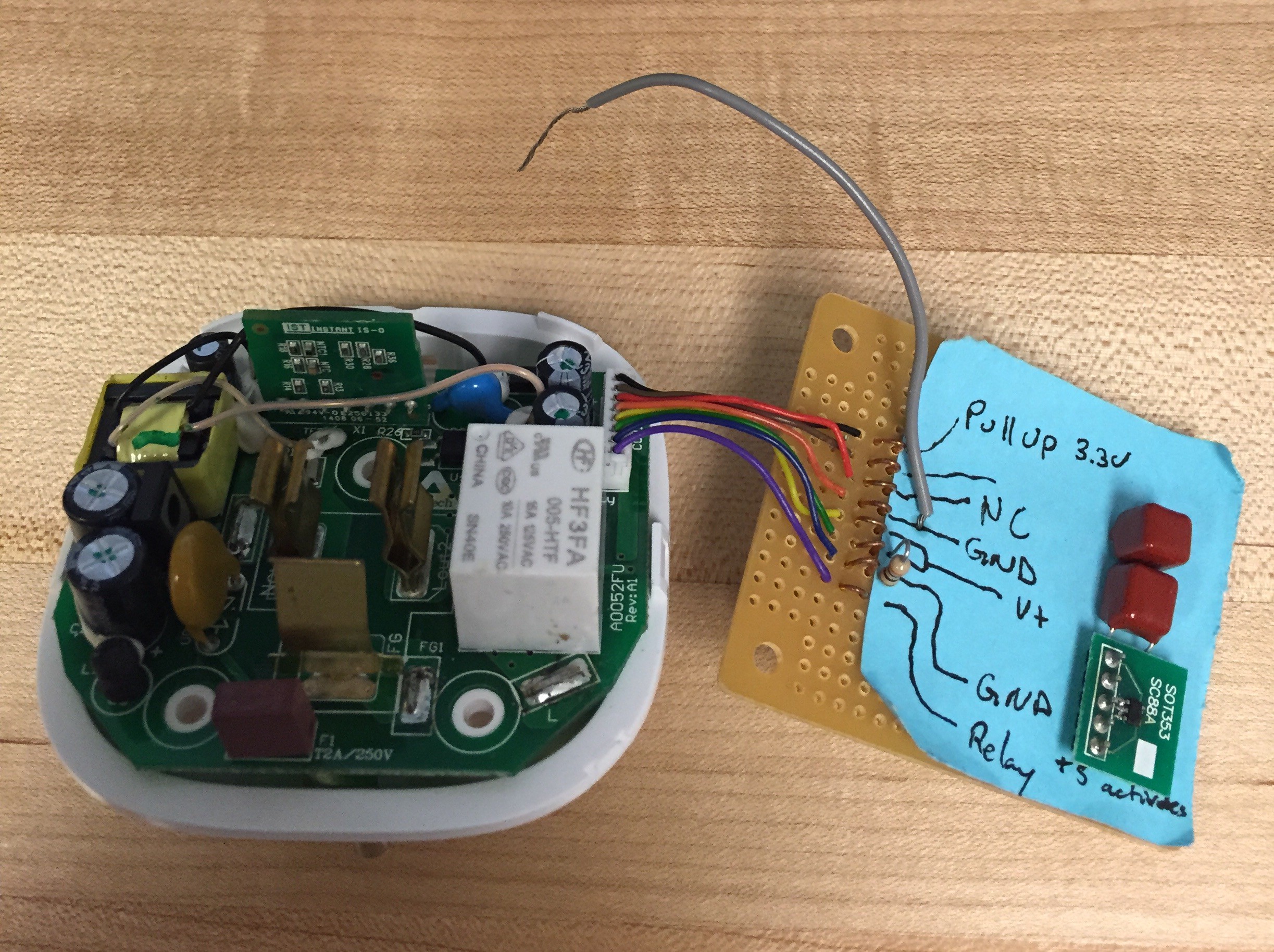
This is a great setup- the control board has an isolated +5V supply, a standard 9600 Baud UART connection to the solid state meter, and a logic level drive for the relay. What more could you ask for? The one trick is the 3.3V pull up on pin 1. The meter runs on its own isolated supply and an optical isolator connects it to the control board. In order for this to work the control board needs to supply a pull up to its side of the isolator, hence the LDO on the "sniffer board".
Stay tuned for more details!!
Discussions
Become a Hackaday.io Member
Create an account to leave a comment. Already have an account? Log In.