 John
JohnDesigning stable firmware for embedded devices is always more complicated than it first appears. The goal with this project is simple - read the solid state meter and toggle the relay ON and OFF over WiFi. Should be easy right? Well....
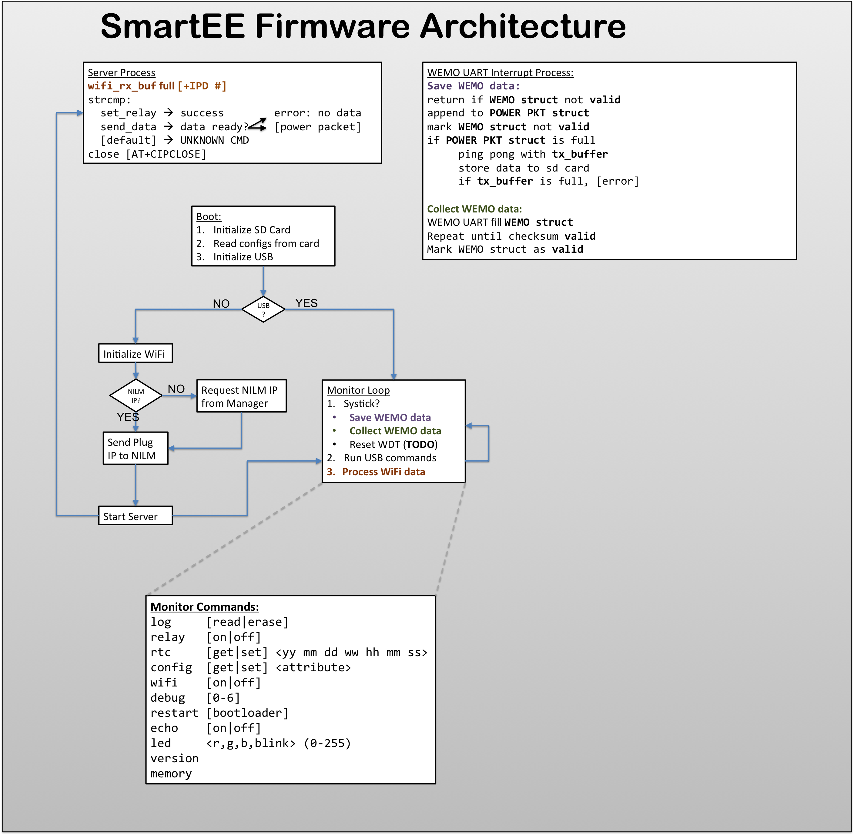
There are three main modules: WEMO interrupt, Server Process, and Monitor Loop
- The WEMO interrupt module records values from the solid state meter. The most recent samples are kept in a buffer and then stored to the SD Card.
- The server module listens for TCP traffic on port 1337 (woot!). Incoming traffic is parsed and if a valid command is received the module executes the request (eg. turn ON relay).
- The monitor loop provides a common systick for the other modules, coordinates their execution and handles USB TTY commands when the board is connected to a PC.
WEMO Interrupts
The solid state meter auto reports data quite fast - several packets per second. This is too much to transmit so only one packet every other second is actually recorded. Sampling at 0.5Hz seems to be a good tradeoff between resolution and WiFi bandwidth. Each time the monitor loop runs it checks if a valid meter packet has been read, if a new packet is ready it is stored in the server buffer and also recorded to the SD card. The monitor then sets up the UART for a new meter reading. Since the meter chip sends data asynchronously to the monitor, the UART might receive a garbled packet depending on when it starts to listen. Fortunately garbled packets can be detected by their corrupt checksums and discarded.
Server Process
The ESP8266 uses AT modem commands which, while simple, are surprisingly tricky to handle in C. Manipulating strings and handling the asynchronous arrival of data requires some careful coding. Oh memory leaks.... The ESP8266 commands are all in [wifi.c] safely abstracting to gory details of AT commands from the rest of the code. Hopefully this will also make it easer to replace/upgrade the wifi portion of this build in the future.
Monitor Loop
The monitor loop is the main [while(true)] loop that coordinates the execution of the other processes. Additionally it handles USB TTY commands which are used to configure the plug and retrieve data. The figure shows some of the supported commands.
Of course you can only really get a feel for the code by looking at the code! I'll be posting the full firmware to the github repository soon!
If you have any questions please let me know!
Discussions
Become a Hackaday.io Member
Create an account to leave a comment. Already have an account? Log In.