 hackhead79
The project will feature a XC9536XL CPLD from Xilinx.
A CPLD is basically a simpler version of an FPGA - both are microchips.
But what is a CPLD or FPGA for that matter and what makes them different from other microchips (as for example the ATmegas and ATtinys from Atmel used in Arduino boards etc.)?
CPLDs and FPGAs basically have 'programmable internal wiring'. That is the chip can be reconfigured via software / programming to do (almost) any task you want it to do.
And how is that different to simply programming an Arduino?
The part that is different is that the reprogramming / reconfiguring happens on the hardware level, not on the software level. So programming happens 'much closer to metal' than 'ordinary programming' (very vaguely like programming a chip in Assembler in terms of 'close to metal-ness').
In other words, programming it does not only mean telling the chip what to do (do A, then B, then C) but it also means telling it how each little part inside is connected with each other part and how these parts work together and at what timings. Timings can be defined down to a few nanoseconds accuracy depending on the chip. With other µCs you ideally have single-cycle execution commands (like with the µCs from Atmel - PICs from Microchip are more difficult here) and factor in the clock speed to take the guesswork out of program timing. And you have to progam them in Assembler which is much too time consuming and complex for most tasks.
A CPLD's / FPGA's highly precise timing allows them to do stuff like producing the video output for a LCD panel or video output in general and their computing power and speed is used in (real-time) signal analysis and processing tasks, image analysis tasks (for example in robotics: object detection, face detection etc.) and also in cryptography (some projects use them as cheap 'supercomputers' to break weaker encryptions).
They have two other significant advantages that make them different by design:
a) different parts of the chip can be assigned different tasks and these tasks can run in parallel! That means where a 'normal' microchip would do task A then B then C one after the other, a CPLD/FPGA would do them concurrently (vaguely similar to a GPU compared to a CPU) and be done in literally a third of the time. The only limit to the amount of tasks is the amount of 'logic gates' or 'logic units' the chip offers (more logic units => higher price) and the (computational) complexity of the tasks involved.
b) they consume relatively little power for the amount of work they can do, provided it is work that can be done in parallel.
As for my choice of device: why a CPLD and not a FPGA?
CPLDs offer less computational resources than FPGAs (from 5-100x) but they also are cheaper in general, not by a large margin though. The cheapest CPLDs can be had for 2-5$ (most in the 2-50$ range), the cheapest FPGAs start at about 5-10$ (up to several hundred dollars, depending on complexity).
Another small advantage, a bit depending on the task: CPLDs have a
quicker startup time since they have an internal non-volatile memory
(i.e. its contents don't disappear on power off) for their
configuration. FPGAs have to read their configuration from an external
flash memory which can take a few seconds on startup.
Since CPLDs are a bit simpler by design as mentioned but are programmed
in the same languages as FPGAs (VHDL and Verilog are the main ones - the
former oftentimes used in Europe, the latter mainly in the US), they
are a good starting point for getting into the world of reprogrammable
or rather reconfigurable microchips (or so I hope). And last but not least, I did not find a good tutorial for a FPGA board ;)).


 Michael Rangen
 Luke Valenty
 Jackson Keating
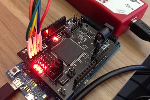
 technolomaniac
For the XC9536XL CPLD, I'm using a PCI debugger that I bought in Shenzhen last year. It also came with a Nokia screen :-).
It's already on a board, and I soldered a JTAG header into place.
http://peterburk.free.fr/Ghuru/CPLD%20Top.JPG
For a JTAG programmer, I'm using the GuzuntyPi gz_load tool on my Raspberry Pi.
I made 2 test programs earlier this year when I was in South Korea, and I had access to a Xilinx USB programmer. Those just turn the LED on or off.
About a month ago, I used my Raspberry Pi to program the CPLD successfully, to my great relief! The LED is on or off as expected.
Do you have any ideas of further projects I can use this for? I enjoy circuit design, and learned Verilog and VHDL in university, but I'm not actually sure what to do with it now.