 Yann Guidon / YGDES
Antti has "optimised" the design to use the as few pins as possible, for example the TRST signal is not routed (Antti justified this because the JTAG protocol always starts with a reset sequence). A pull-down resistor on the TCK pin would be great, but I don't have the detailed schematic of the board... Which becomes problematic because I don't know what's going on with the VPUMP and VJTAG pins. I can only suppose they're internally tied to 3.3V because TDO gives this voltage.
I've had quite a few weird problems with this board : first, I think it's preprogrammed so the initial configuration creates conflicts on I/O pins andthis increases the current draw (until a new configuration is flashed).
The connections are not great but I managed to solder them.
Another gotcha is related to chaining : one FPGA's TDO goes to the next FPGA's TDI. However, the JTAG signals do not invert the names ! The probe's TDO signal goes to the FPGA's TDO output, and the FPGA's TDI input is tied to the probe's TDI. Go figure.
But something more troubling happens with my FlashPro3 JTAG probe : connecting the probe to my circuit, where the VPUMP and VJTAG are connected to the FPGA's 3.3V supply rail, drops the 3.3V rail to about 1.8V. During the connection event, the scope shows a short-like drop with a slow recovery but that never reaches the expected 3.3V.
The short-like condition occurs even when the circuit is running, after programming, which creates weird behaviours. The probe must be removed, disconnected, to allow the circuit to work right again. I'm not able to measure the currents but I suppose it would be in the hundreds of mA, which can make my LDO warm...
I tried to "isolate" the VPUMP signal, through a 2K resistor : it's enough to "sense" the target's 3.3V supply yet prevent the FlashPro3 from drawing current. But it didn't work so VJTAG is causing this too.
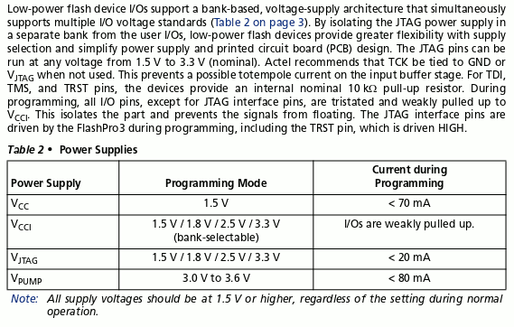
This does not make sense, considering the data provided by Actel in Actel_ISP_HBs.pdf in Table 2 • Power Supplies :
VJTAG : 1.5 V / 1.8 V / 2.5 V / 3.3 V < 20 mA
VPUMP : 3.0 V to 3.6 V, < 80 mA
VJTAG shouldn't draw so much current that the 500mA-capable LDO drops don't to 1.5V...
I can't isolate VJTAG with another resistor because that signal is used to power the drivers that talk to the FPGA chain.
Is it a problem caused by the newer version of FlashPro v9 software ?
I couldn't test with the FlashPro4 probe (which is at home).
The couple of Stamps are programmed anyway so I don't need to solve this ASAP but it's still a burning issue...
Still battling the power supply issues.
I found that the next generation device : FlahsPro4 uses the last free pin to toggle the power supply:
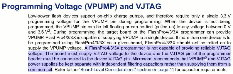
 I haven't found yet the schematics of the FP3 circuit though. I just found this mention though :
I'm wondering if the problems appear because there are 2 chained FPGA. I'll split the JTAG chain to see if it solves the problem.
I hooked a lame "loopback" circuit to the FP3 and the FP3 still works (I feard I burned something). Something else must be going wrong. But the loopback works : on it, VJTAG is directly fed by VPUMP, which is 3.3V and can source 80mA. So this might be the key !
Instead of just isolating VPUMP from my VCC, through a resistor to allow autosense, let's just keep VPUMP and VJTAG tied together, isolated from the rest (and no resistor to prevent autosense).
The only problem is : chain scan fails with the loopback circuit...
"Vjtag is diconnected or shorted. Please check that the target board is powered"
It appears that VJTAG is tested before VPUMP is applied. So VJTAG must be pre-powered, but it sinks quite a lot of current, and VPUMP can't be powered as well because this would prevent VPUMP from providing the power for the rest of the sequence.
Anyway : Loopback testing is a good starting point.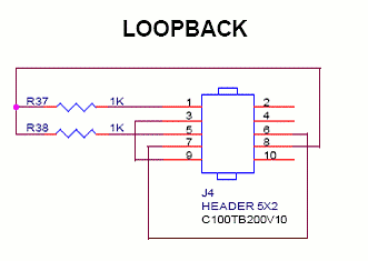
So now what are the electrical properties ?
VPUMP : inactive : 17K ohms toward 0V.
VJTAG : disconnected: 1M -> 0V, connected/inactive : 2.2V, 1µA short current to 0V.
This is not coherent with my measurements... so why does my circuit's supply drop ?
Note : I measured the currents and found that the couple of FPGA draw 30mA together.
Then when I connect the FP3, current rises to 40mA (only ?) and the 3.3V rail shortly drops to 0V and slowly (several ms) rises to about 2V... so something might be wrong with my circuit.
Case closed : I mistook a pulled-up configuration signal for a 3.3V rail wire... this explains all the symptoms but I didn't measure enough parameters before trying to diagnose the problem :-(
So yeah, if your 3.3V rail is not shitty, just connect VJTAG and VPUMP to it...
Discussions
Become a Hackaday.io Member
Create an account to leave a comment. Already have an account? Log In.
good luck !
Are you sure? yes | no
Tak for the helpful support !
Are you sure? yes | no