Close
0%
0%

Little 0-24V power supply based on LM317T

Adjustable power supply 0-24V (1A) based on LM317T.

Similar projects worth following
little practical power supply and goes everywhere.

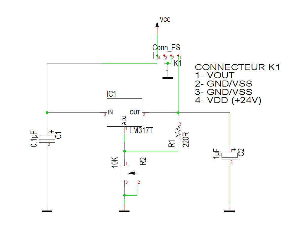
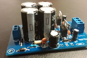
It's a little montage that serves me in many projects, the input voltage (Vin) accepts an industrial voltage 24V (max), the output is adjustable from 0 to Vin with the potentiometer R2.
Connector K1 is more useful to be installed in its bent 90 ° version, making this power supply not greedy on space. (vertical installation on a breadboard or soldered on a motherboard mounting)

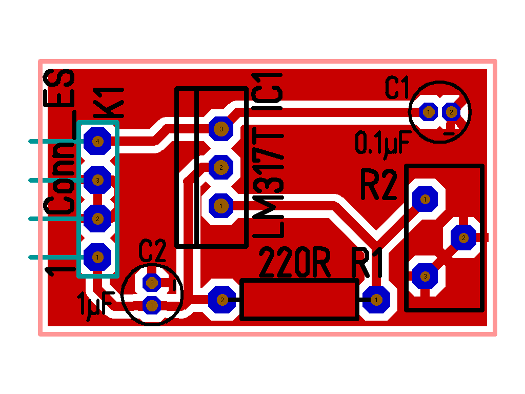
The PCB is only 30 x 18 mm, and dimensions can be further improved, however, if it interested someone.
Another possible improvement is to use SMD components to further reduce the footprint of this circuit.

Just a small contribution to start, I hope it will serve the greatest number.

Enjoy !

  • 1 × 0.1 uF polarised condensator C1 : C_ELKO_GRILLE1.5_DIAM4
  • 1 × 1 uF polarised condensator C2 : C_ELKO_GRILLE1.5_DIAM4
  • 1 × LM317T IC1 : Linear Voltage Regulators TO220
  • 1 × 1 x 4 pin header K1 : 1X04-90° connector
  • 1 × 220 Ohm Resistor R1 : 0207 pinout

View all 6 components

View project log

  • 1
    Step 1

    Schematic:

  • 2
    Step 2

    PCB and placement :

  • 3
    Step 3

    List of components

    Name Value Case Q
    C1 0.1µF C_ELKO_GRILLE1.5_DIAM4 1
    C2 1µF C_ELKO_GRILLE1.5_DIAM4 1
    IC1 LM317T TO220 1
    K1 Conn_ES 1X04-90° 1
    R1 220R 0207 1
    R2 10K POTI_3386H 1

View all 3 instructions

Enjoy this project?

Share

Discussions

Electroniclovers123 wrote 09/15/2021 at 09:22 point

The LM317T can also be wired as a 1.5A constant current supply.With a short circuit across the output, the resistance between OUT and ADJ should be approximately 750 milliohms, 2W or two 1.5 ohm, 1W resistors in parallel to limit the current to 1.5A. Higher resistance reduces available current.The LM317T can only dissipate 3W of power in air. If the voltage across it multiplied by the conducted current is higher, it will be necessary to install a heat sink.

  Are you sure? yes | no

K.C. Lee wrote 05/31/2017 at 13:19 point

Unfortunately, you won't be able to get to the full range at 1A because the LM317 will have to dissipate the voltage drop * current as heat. That layout is not designed for mounting a huge heat sink.

In reality, a bare TO220 has theta JA of 40C/W, so each watt of power it dissipate will increase its temperature over the ambient by 40C.  So a couple of watts is all it can take on tis layout.  You are looking at over 100C already.  :P

  Are you sure? yes | no

euchcat wrote 05/30/2017 at 21:28 point

Yes, to get the LM317 down to zero volts you need to bring the control pin down to -1.25 V.

I will correct the schema as soon as possible! (i'm very busy sorry !) 

  Are you sure? yes | no

Tron9000 wrote 05/31/2017 at 11:31 point

lol no need to apologie to me, its your project, you take as long as you like!

  Are you sure? yes | no

Malhar Deshmukh wrote 01/20/2016 at 10:52 point

How did you achieve 0 v? LM317 can go down to 1.25 v only?

  Are you sure? yes | no

euchcat wrote 01/20/2016 at 19:35 point

Yes empty you can not drop below 1.25V, but the circuit in charge as soon as the consumer is sufficient we reach down to 0 volts ....
I use this circuit to power coils and I have no problem to adjust the low, depending on the type of coil, consumption is quite large.
Best regard.

  Are you sure? yes | no

Tron9000 wrote 05/30/2017 at 11:50 point

I too am I bit confused how you intend this to go down to 0V. The minimum output of an LM317 in this configuration is 1.25V, but you can make it go dwon to 0V if you bias the adjust pin resistor to -1.25V-ish

  Are you sure? yes | no

Similar Projects

Does this project spark your interest?

Become a member to follow this project and never miss any updates