 Nick Sayer
I'm undecided whether I'm going to do this or not, but I had an e-mail conversation with Jim yesterday where we discussed a change he made in his design that aimed to make the phase discriminator output more linear.
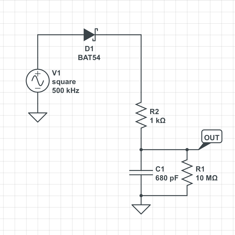
To recall, the phase discriminator effectively times the leading edge of a 1 MHz clock derived from the oscillator relative to the PPS signal. The output of the phase discriminator is a pulse between 0 and 1 µs wide. That pulse is translated into a voltage with a Schottky diode, and an RC network with a "bleed" resistor across the cap to insure it's discharged by the time the next PPS interval arrives. Here's the schematic:
And here's a simulation of it:
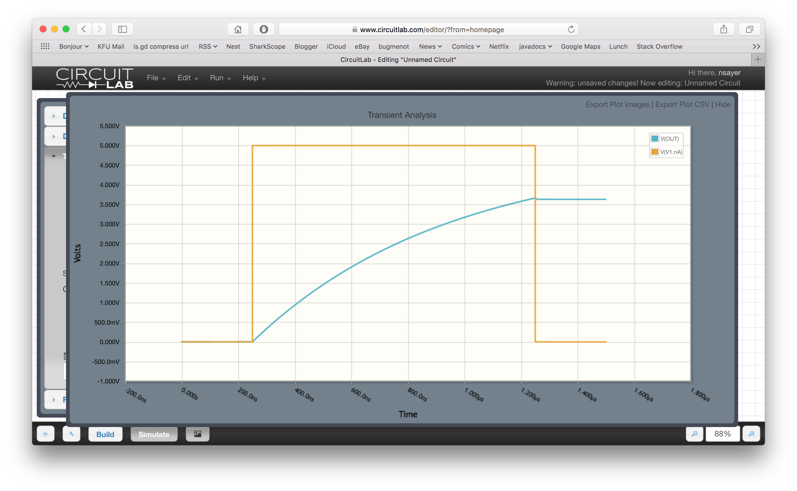
The maximal width pulse is the orange line, the output voltage is the blue one. You can clearly see the non-linearity of the curve. For the GPSDO, it doesn't really matter all that much, because the goal is to try and constrain the oscillator towards the middle of the graph.
But what this means is that you can't use the actual ADC values that are logged on the diagnostic output for anything real without scaling out the non-linearity.
It turns out that by adding a single part, this can be improved:
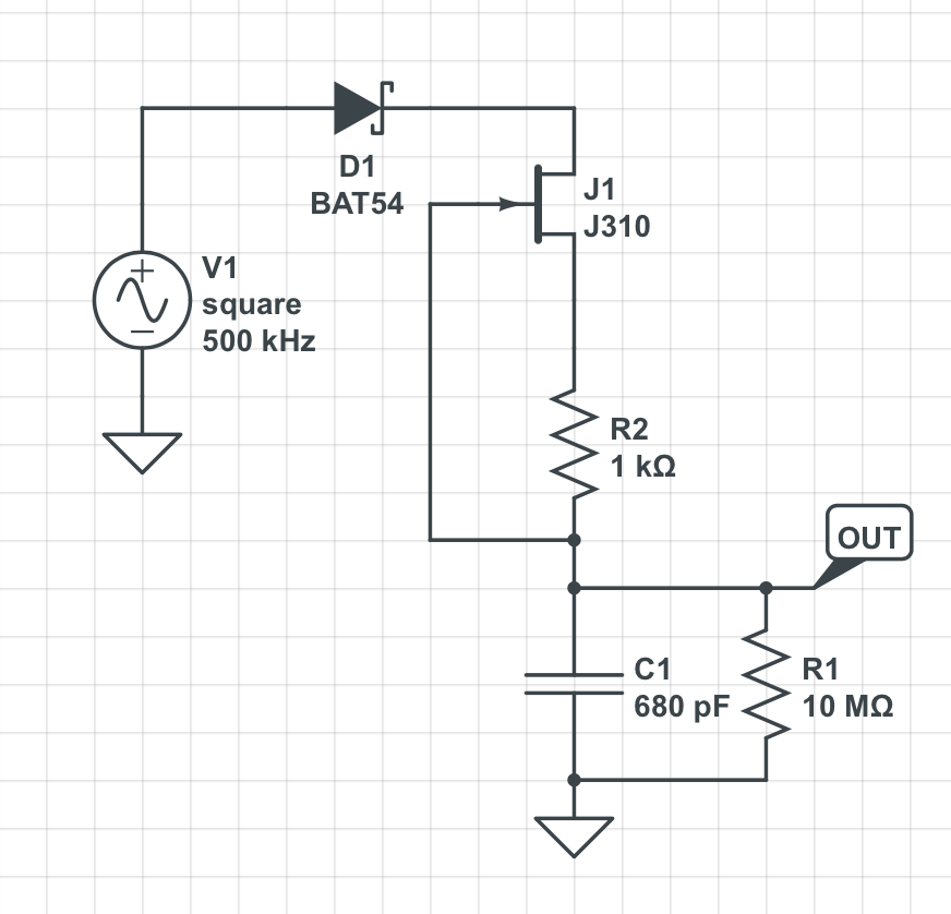
The JFET acts as a current regulator. The result of adding it is this:
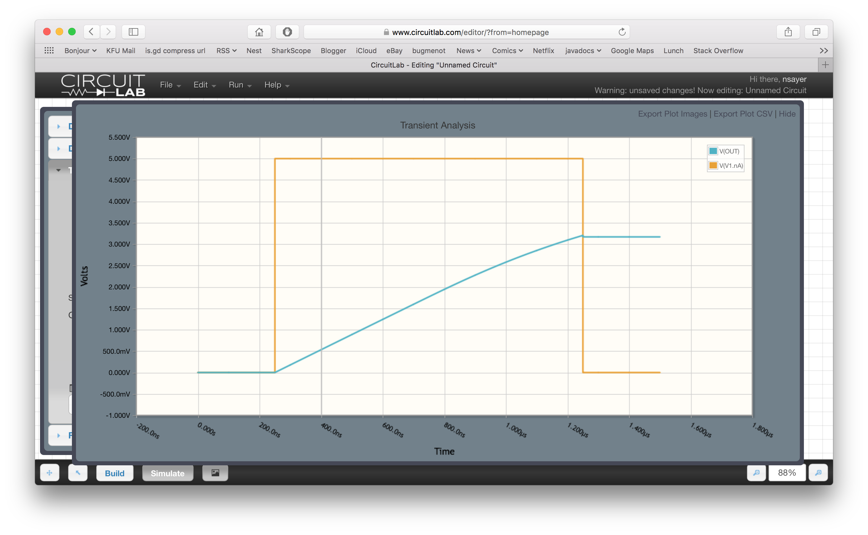
That's a much straighter line. It's not perfect - there's a little flattening near the top, but you have to balance the voltage range (the larger the range, the less noise there will be) against running into the "pinch off" point of the current regulation.
I'm kinda torn on this one. It's not a big change, and it's not very expensive, but it's not something absolutely required. At the same time, I can understand it being something that some users might like if they want to gather lots of stats.
Anybody have any thoughts?
Discussions
Become a Hackaday.io Member
Create an account to leave a comment. Already have an account? Log In.
Since you known the transfer function on how the pulse width affects the voltage, can't you linearize it in firmware as you already use an ADC to read it and close the feedback loop? A simple piecewise linear interpolation look up can convert that.
Are you sure? yes | no
Believe it or not, we're beginning to run out of space in the firmware. You could just as easily post-process the values on a host computer, of course. It's just a matter of whether an extra 30¢ part to flatten that curve is worth it.
Are you sure? yes | no