 The Big One
Something is wrong with the boards, but I can't for the life of me figure out what it is.
The issue appears to be in the peak hold circuitry. This is where the peak of the waveform is held at a constant level for downstream amplification and sampling. THe circuit is quite simple, and consists of an op amp, schottkey diode, capacitor, with a couple of resistors to help condition the piezo signal before going into the opamp.
When protoyping, everything worked fine with this. Adjusting the capacitor value would affect the falloff rate of the peak; a 0.1uF would take a couple of seconds to go down, and a 10nF would take maybe half a second or so. The design used 10nF caps, as this was plenty of time to do the ADC sampling.
Well, after I got things soldered up, I plugged it in, and I couldn't get a signal for the life of me. Some troubleshooting found a few solder problems, which I fixed. I was now seeing the signal pass through, but the peak hold was not working - the waveform looked very similar to my original Drum Master board, where the pizeo was rectified and low pass filtered, but only with a diode + RC network, no active hold circuit.

Discouraged, I re-implemented the circuit on a breadboard, to make sure I had done it right. It worked there.
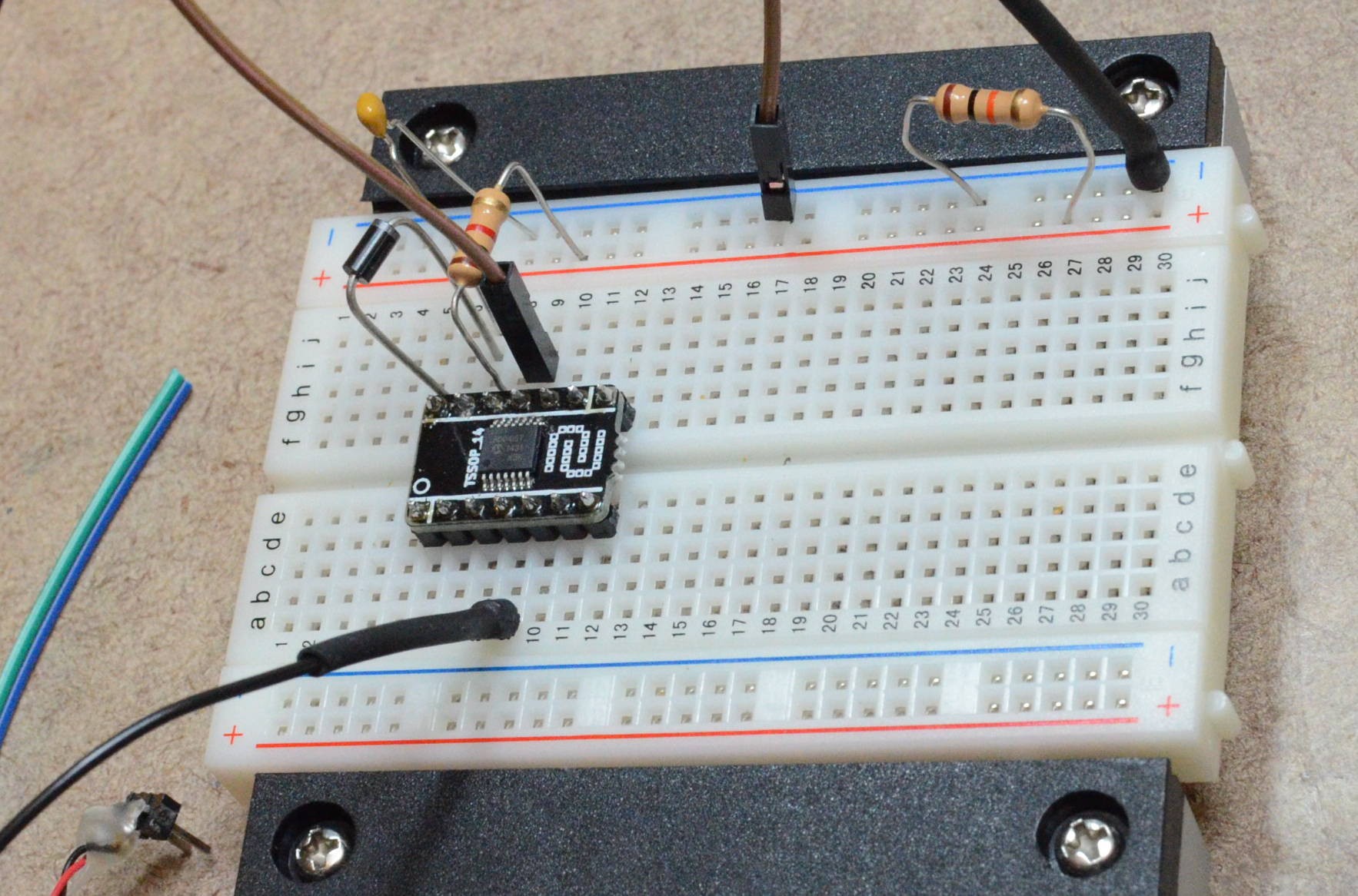
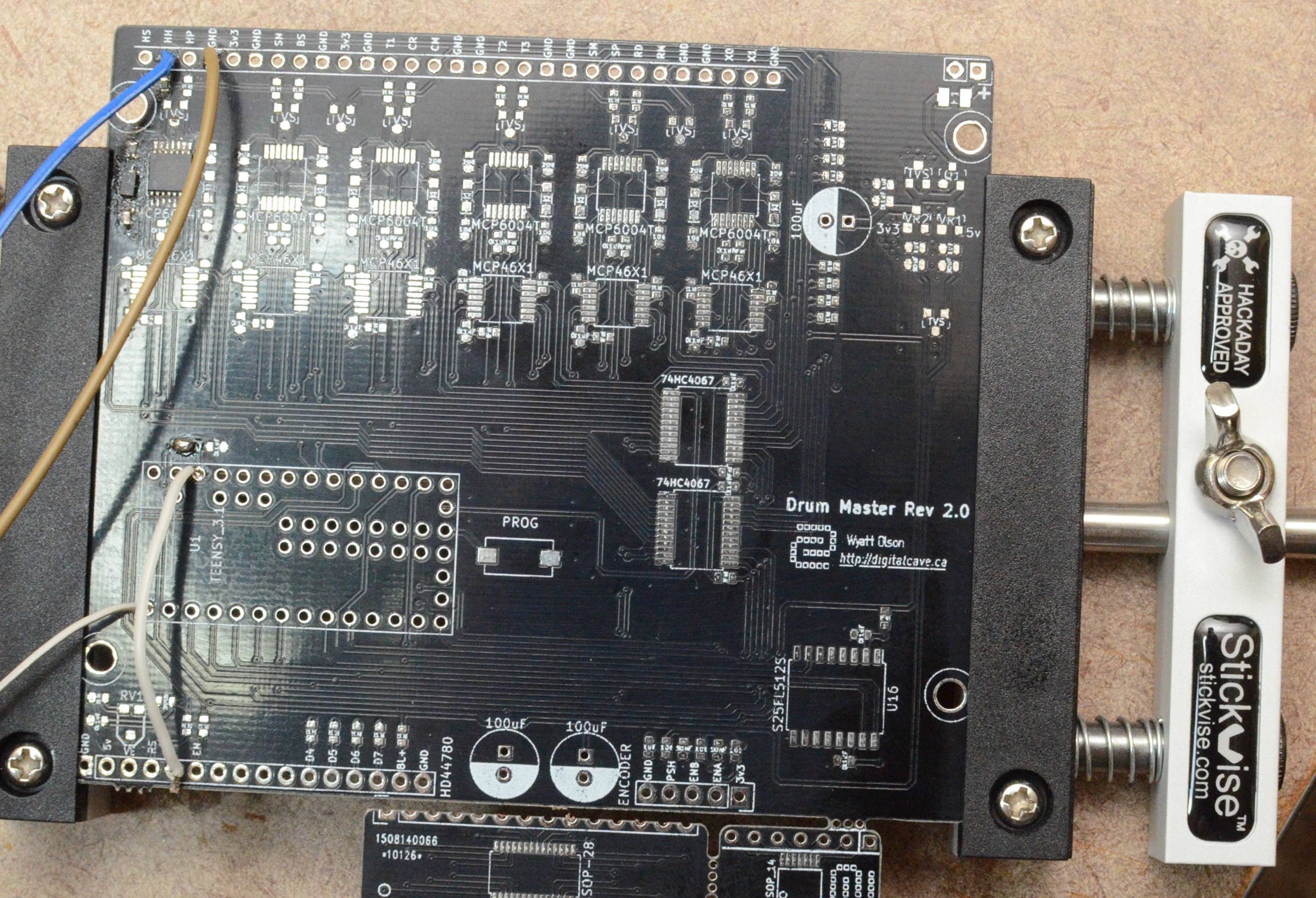
I then tried soldering up just the peak hold circuit on another copy of the board, in case there was some soldering issue or something that I had not seen... nada. Still the same results.
At this point I am at a loss of what to do. I can't think of any rational explanation for why it works on the breadboard and not on the real circuit. I have repeatedly checked continuity between critical points, checked the component values, checked for shorts, etc. The only differences I can think of are that I am using a different diode on the SMD version, which has slightly less forward voltage, but given how it is configured in the op amp circuit this should not have any impact. I suppose that parasitic capacitance on the breadboard could be making things different, although normally that would cause problems, not make things work. Furthermore, the design checks out in Falstad's simulator, and I would not expect this to be the case if it were a very finicky circuit which relied on parasitic capacitance.
If anyone has any thoughts on what could be wrong, please feel free to let me know. I am getting frustrated; it's been a whole week fighting these problems, and I am pretty much out of thoughts on what could be wrong.

(Some of my ugliest soldering - it looked good originally, but during troubleshooting I tried changing the values of a number of resistors + capacitors, and my re-work skills are not quite up to par...)
Until next time...
Cheers
Discussions
Become a Hackaday.io Member
Create an account to leave a comment. Already have an account? Log In.