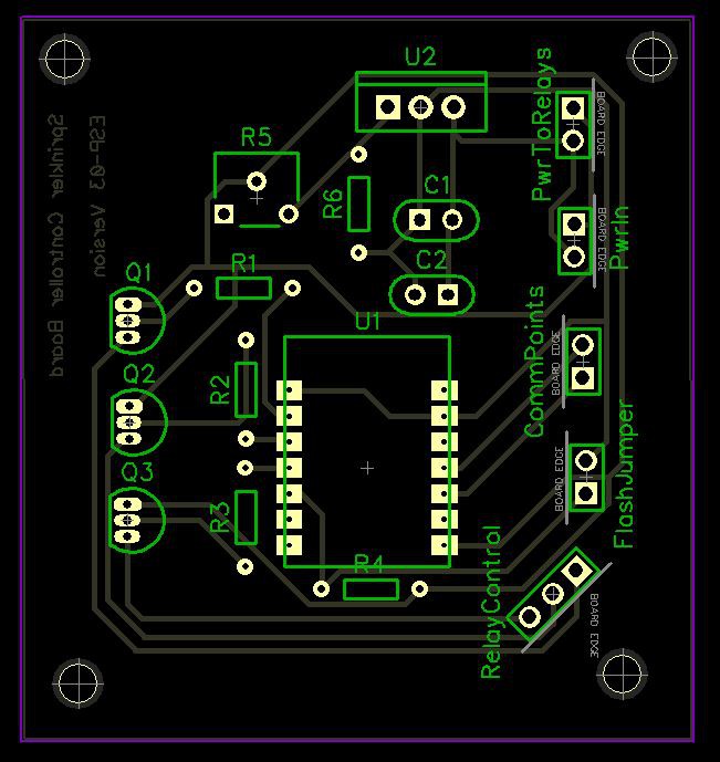
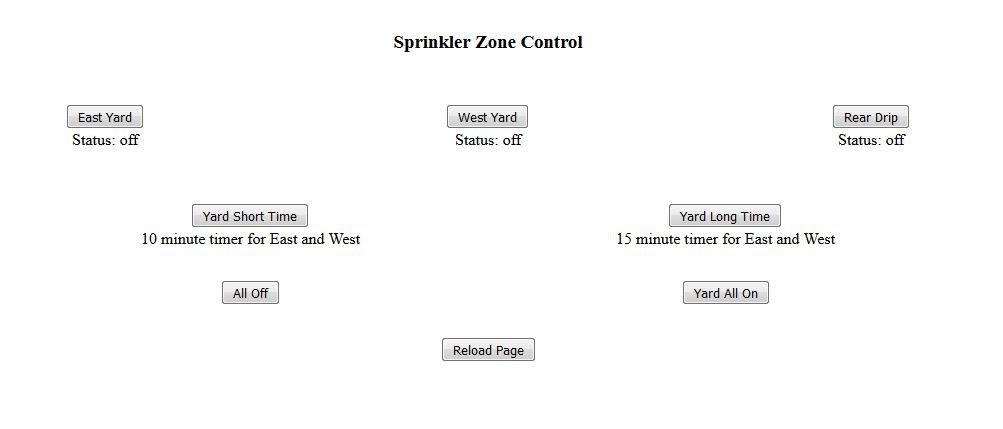
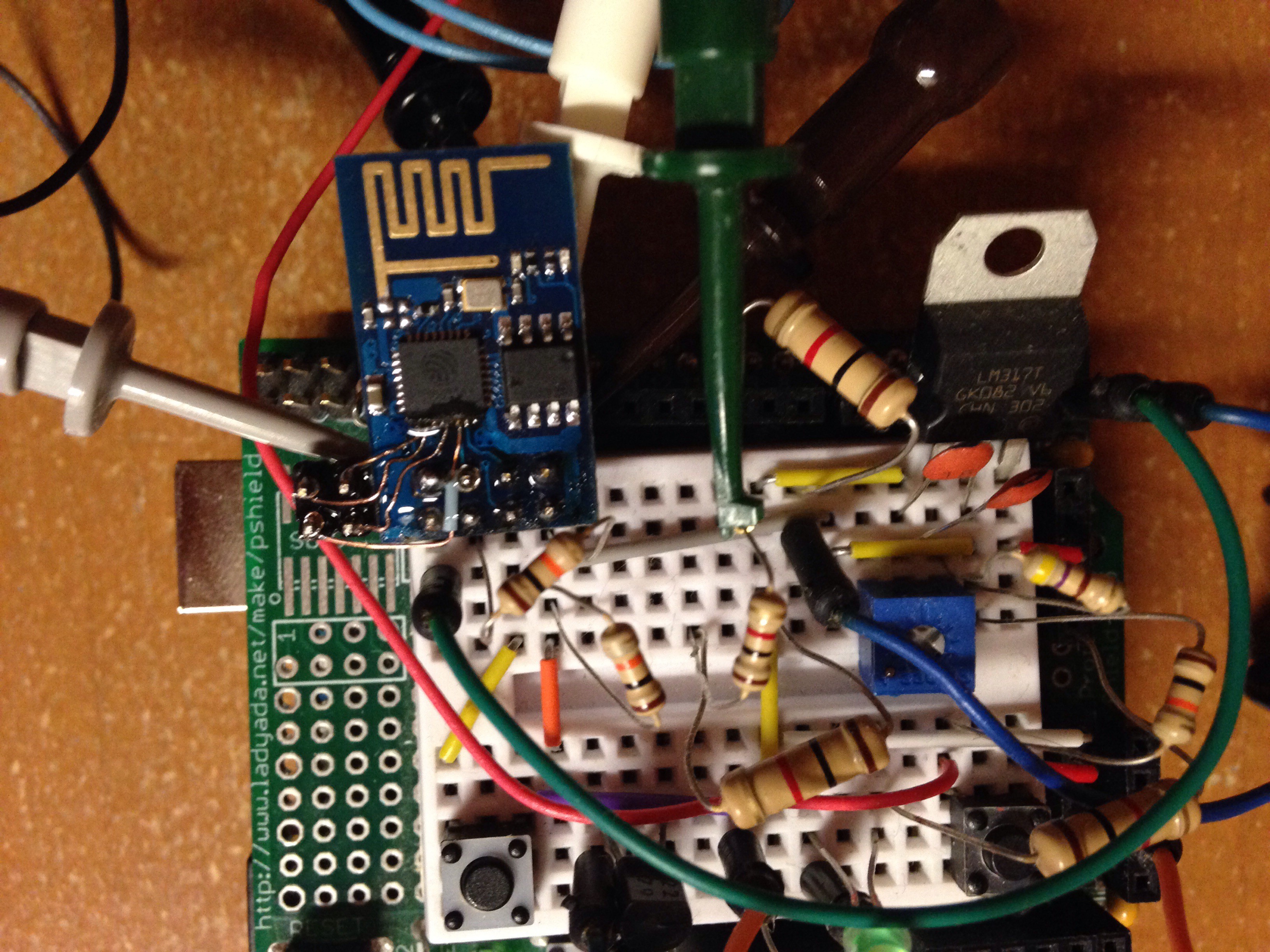
• ESP-01 Died

    zacnotes08/25/2015 at 20:10 0 comments

    So I had 2 ESP-01's on hand, and I managed to kill both of them. I was struggling to have the ESP fire the relays while they had a load across them, and it was resetting the ESP every time I tried. Looked to me like the relay power draw (same wall wart powering both the ESP and the relay board) was enough to kill the ESP when the relay fired under load. In my misguided attempts at correcting this, I managed to burn out both ESP units. They communicate over wifi and serial still, but it is iffy, and new programming will not take.

    While I was congratulating myself on a job well done with the sprinkler controller, and had plans for the second ESP-01 board as well (all before frying them), I had put in an order for 2 more ESP units, this time the -03 variant, just to have on hand in case the muse strikes me in the future. I could have bodged on some manner of header that allowed me to plug the ESP-03 units into the socket I had worked up on the original sprinkler board, but I didn't really like that idea. I designed a whole new board, based around the ESP-03, and as I didn't want to wait for OSH Park, I just etched it at home. the board design:

    I have done a number of successful double sided boards at home before, but it does take some time, and there is a significantly increased chance of board error, so I did this one single sided. That means the surface mounted ESP-03 unit is on the back of the board, and all the other components are on the front. The board came out of the wash just fine, and I had it populated in no time. I swapped out the original 750ma 5V power supply that was used on the first board for a 2A 5V unit I had in the scrap bin. It is likely overkill, but it works like a charm.

    The new board has been in place for about a week now, with no required resets. Seems very stable, and works great. I updated the html as well:

    I will add some scheduling functionality at some point in the future, but while I still need to bring the dog in manually, and close off the doggy door, this solution works fine. Maybe some sort of dog call + dog presence sensor + auto closing doggy door coupled with the sprinkler schedule for a future project.

    I am going to mark this project as complete, although it does miss one of the original design goals of having a scheduling system.

  • I/O expansion

    zacnotes07/28/2015 at 04:36 0 comments

    double row headers showed up today, so I made a successful attempt at connecting to the 4 additional 'easy' pins to reach.

    First, I removed the 8 pin header, to give me a little more room to work with. Next was soldering jumper wires to the I/O pins on the ic. I don't have a solder tip small enough, so I did the copper wire wrap trick. Worked really well. Next was adding the new header. It was here that I realized an error in my pcb design. There are 2 empty pin slots in the new header, to get the new 4 pins out past the ESP pcb. Also, I put the pins on the wrong side on my pcb design. Good thing my connector is wire to the board. I can correct my mistakes there.

    Next in the I/O expansion was to connect the jumper wires to the new header. I routed the wires to the header, being careful to pinch the wire against the pcb while bending, so as not to stress the tiny solder joint. I wrapped the wire around the top of the new pins, and tried to solder the points very quickly, attempting to keep the heat from traveling up the wire and disconnecting the joint at the ic. Only one wire became disconnected, and I was able to repair it without trouble. I then fired the unit up, and it threw a comms error. Blue light came on solid. I believed that one of the new I/O points was connected to one of the pins next to it (not I/O to I/O, as I had continuity tested those.) I cleaned up the joints at the ic with my wire wrapped iron, and powered on again.

    Success!

    I tested each of the new pins, all were firing as expected, so I dabbed on some superglue to assist the tiny wires. Now we wait for the pcb from osh park.

  • Software Update

    zacnotes07/26/2015 at 16:45 0 comments

    I decided that there was no reason I couldn't continue work on the software as I waited for the hardware to show up. There is now a simple timer that runs each zone for 10 or 15 minutes, depending on the selection. This will probably be the first edition actually in use, unless I can get the next part figured out in a week and a half. While that is neat, the real excitement is in what I am working through now.

    The issue previously was the ability to push the whole webpage from the esp to the browser. I have managed to put the html file in my Dropbox, and call for it as an html object, and have the full page available. The problem is that as an object, it has it's own window inside the browser, and I can't manage to set the height to 100%. Width sets no problem. So I have a 400 pixel tall box from one side of the browser to the other, with a scroll bar on the side. I found some reference to the fact that the <html> tag needs to be set to 100% with css, but I have not managed to make it work yet. Input is welcome.

    Related; I don't know if the button responses will report to the esp from an object hosted elsewhere. May be another hurdle.

  • Board en route

    zacnotes07/23/2015 at 19:35 0 comments

    Decided to design up and order a board from Osh Park. $12 bucks and a little wait time is worth it. Instant gratification be damned.

  • No more Perf+

    zacnotes07/23/2015 at 04:09 0 comments

    Well, I gave it a solid try, but I don't think I can play nice with the Perf+ board. Granted, it has been some time since I have used any kind of perf board, I tend to either make my own board or have it made at a board shop, but I can't make that tiny footprint work. I have attached a picture with a half watt resistor lead going through one of the holes, attempting to show that it barely fits. Not that I have any 1/2 watt resistors in this project, but the point is: every hole is tiny. In the Perfy software help file (they are not affiliated, for what that is worth) there is a suggestion that you solder pad to strip connections prior to placing components. This is fine for the "vias", and the help file says to avoid soldering over the holes where components go, but i found it impossible to make the jump from strip to pad without covering the holes. The amount of solder required to make the jump automatically filled the hole as well.

    I think i would have found it easier if the strips were connected to the holes, and you had to cut lines that you don't want connected.

    Either way, I thought I had a regular single sided breadboard laying around here, but I can't find it.

    Till tomorrow.

    Zac

  • Simple Sprinkler almost done

    zacnotes07/22/2015 at 22:51 0 comments

    After banging my head on a wall trying to get all the features I want in the end result out the door on the first go, I have decided to get a preliminary unit up and running with just a few simple commands. The hardware should not need to change, so I should be able to just work on the software of a second ESP unit, and when I get it running, swap the two of them out.

    The path to where I am now:

    • Program an arduino to speak with an ESP over AT commands. I couldn't really ever get this one going.
    • Program an ESP with the arduino ISP. I struggled to get the IDE to talk to the unit. I don't recall ever getting it to talk even once.
    • Program an ESP with the nodeMCU platform - works like a charm. The only problem is, I am what you would call a super-amateur programmer, so learning the Lua language and formatting is a bit of an uphill battle. There seems to be plenty of online documentation to assist, however. I am writing code in notepad++, and uploading with the LuaLoader software.

    I have a proof-of-concept piece breadboarded up, as shown in the picture. The arduino is just there as a form of 3.3v and serial comms.

    The other picture is of a program, Perfy. I backed the perf+ kickstarter, and got the boards a little while back. I thought this would be a good chance to give it a test run. The immediate problem I see is that the through holes are smaller than on a standard perf board. The Perfy program is handy, but with the current iteration, there is no way to mark what pads are for what devices, so if you are trying to pack it in tightly, it is tough to remember where exactly all the components go.

    The troubles I am having with the remaining featureset seem to all stem from being able to serve the webpage with all the relevant info on it. The nodeMCU firmware is limited to 1460 characters at a time in conn:send, or the buffer, and while I can successfully break up the HTML code into separate chunks, and send them consecutively, that only works for a little while. I can't manage to get all 5.5k characters out the door.

    Attempts:

    • Creating separate buffer variables, and sending them one after the other
    • conn:send (first 1400 characters) conn:send(second set of 1400 characters) etc. This one works up through the third set of 'send', but hits a timeout, or something. Last 2/5 of the page won't send.
    • Creating separate 'pages' for each zone, as separate .lua files, all pointed at from a main page (.lua file). I think I ran into some global/local variable issues, but I haven't dug into it too much yet.

    Hoping to have the perf board soldered up today, awaiting a new 24vac adapter to show up on Friday. I also need a new enclosure to put on the wall, but the HomeDespot should have what I need.