 Eric Hertz
While I like the "etch-a-sketch" idea, being hand-drivable, this is definitely intended to be motor-driveable. Part of the goal is to aid in the porting of the motion-control aspects of #commonCode (not exclusively for AVRs) over to the PIC32...
This could be considered a continuation, of sorts, from #operation: Learn The MIPS (PIC32MX1xx/2xx) which has been a reasonable success; its heartbeat fades based on a timer, and I've even managed to finally get the LED pin shared with a pushbutton. In other words: the default 'heartbeat' commonCode starting-point/example is now fully-functional on PIC32, which also implies several other commonThings--'tcnter', 'hfmodulation', 'bithandling'--are also functioning on this new MCU architecture. WOOT! The next step is usually the bitbanged-UART 'polled_uar/t', which is really just a tiny extension from heartbeat; using tcnter for precision-timing, and bithandling for... guess. (done and done). After polled_uar/t I usually begin a new project.
So, here we are... a new project! Again, this'll be a porting to PIC32 (aka 'abstracting') of several additional commonThings, including:
- 'pwm' (can this be "ported", really? As-written It's pretty specific to AVRs' timer/counters)
- 'coordStuff' (32-bit integer-coordinate system for up to 255 axes)
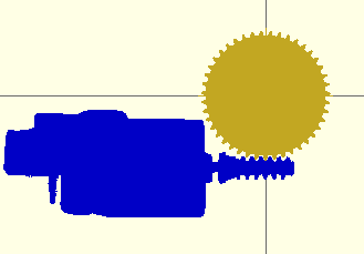
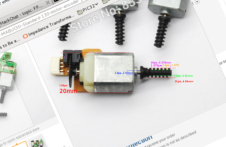
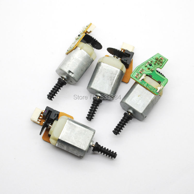
- motorPoxn (designed for DC-motors with an encoder)
- (I didn't commonFile 'encoderDirect'?!)
- polled_uar/t
At which point I'll be able to control the positions of the motors via a computer's serial-port... Later, I might even implement the full motion-system which includes syncrhonization of ramped-axes, arcs, etc... from several other commonThings including:
- sineTable (a lookup table of Sine values, specifically designed for integer-math)
- sineTravel (for arcs and ramping)
- xyTracker (which creates integer-based linear motion along several axes)
- gotoPoxn (which synchronizes motion between motors on up to 255 different axes, regardless of unpredictable/varying loading)
- gotoRamped (which uses sineTravel for ramping/accelerating/decelerating linear motions)
This project has taken on a new life as early design-goals were motivated, in part, by limited prototyping-budget. I visualize an entire (tiny) 2-axis Cartesian system requiring little more than:
- a single 7.1in x 7.1in sheet of laser-cut acrylic (or plywood, etc)
- cable (braided fishing-line)
- pins (for laser-cut wheels/pulleys, most likely just snippings from paper-clips)
- and possibly glue (though, ultimately it'd be pretty cool if it was entirely snap-together)
I visualize a kit, of sorts, distributed in a single 7.1in x 7.1in sheet of material, and a baggie with paper-clips and cable... A 'business-card', maybe?
A separate add-on could then be snapped to it with motors, etc. for computer-control.
Of course, for the purposes of porting the motion-control system to PIC32, that motor-add-on is necessary early-on ;)
Log Highlights:
PWM vs Pulse-Density Modulation: Power Supplies and Big-Ass Capacitors


 Sci
Sci
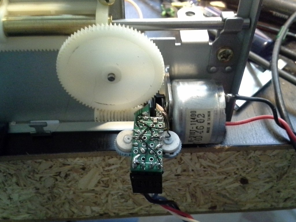
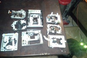
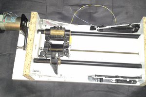
> an old pen-plotter given to me years ago. Years after we parted-ways, I figured-out how they managed to drive two axes with stationarily-mounted motors, pulleys, and cables.
I've disassembled a few and always found the cable system interesting. I don't know if it works the same way, but it reminds me of CoreXY.