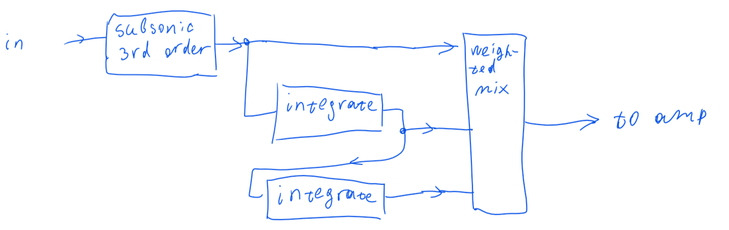
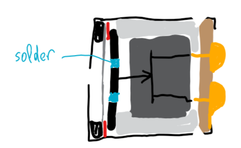
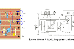
Close
0%
0%

Feedbass! (microphone in loudspeaker)

Using a microphone in speaker cabinet as feed-forward, to extend low frequency range of audio system

Similar projects worth following
Small loudspeakers are notorious for lack of bass. Their typical frequency response features a resonance at around 300 hz, and in lower frequencies the response rolls off as f^2. I am trying to alter the cause of the resonance, to shift it into lower frequencies, or even eliminate altogether.

Resonance involves a mass and a spring. In case of a loudspeaker, the mass is the cone, and the spring is cone suspension and air in cabinet.

With a microphone, the force created by one of these "springs" (the air) can be measured, and extra current can then be sent through the voice coil to compensate for that force. This should shift the effective resonance down in frequency, and thus extend frequency response.

The schematic.

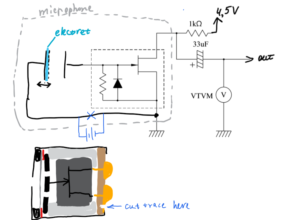
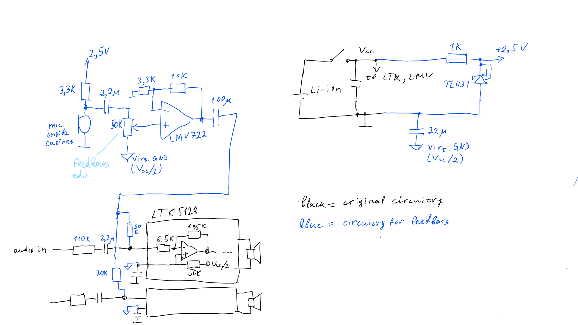
It's quite simple. Signal from microphone placed inside speaker enclosure is amplified and fed into the amplifier. If the feedback direction happens to be negative, it's easiest to swap driver polarity.

The potentiometer adjusts the depth of microphone positive feedback, which changes the amount of bass boost. If it's adjusted too high, the system starts to self-oscillate. Back off a little bit till the oscillation is extinguished, and that is the setting for maximum possible bass boost. 

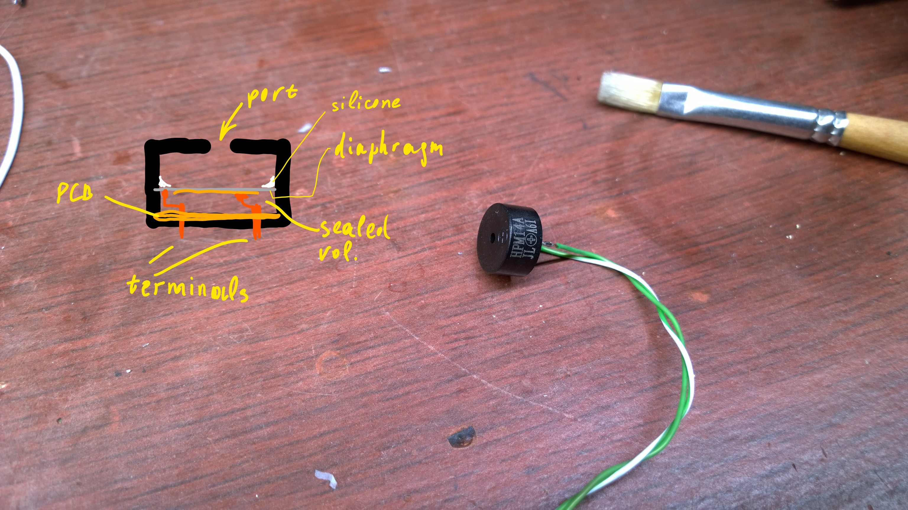
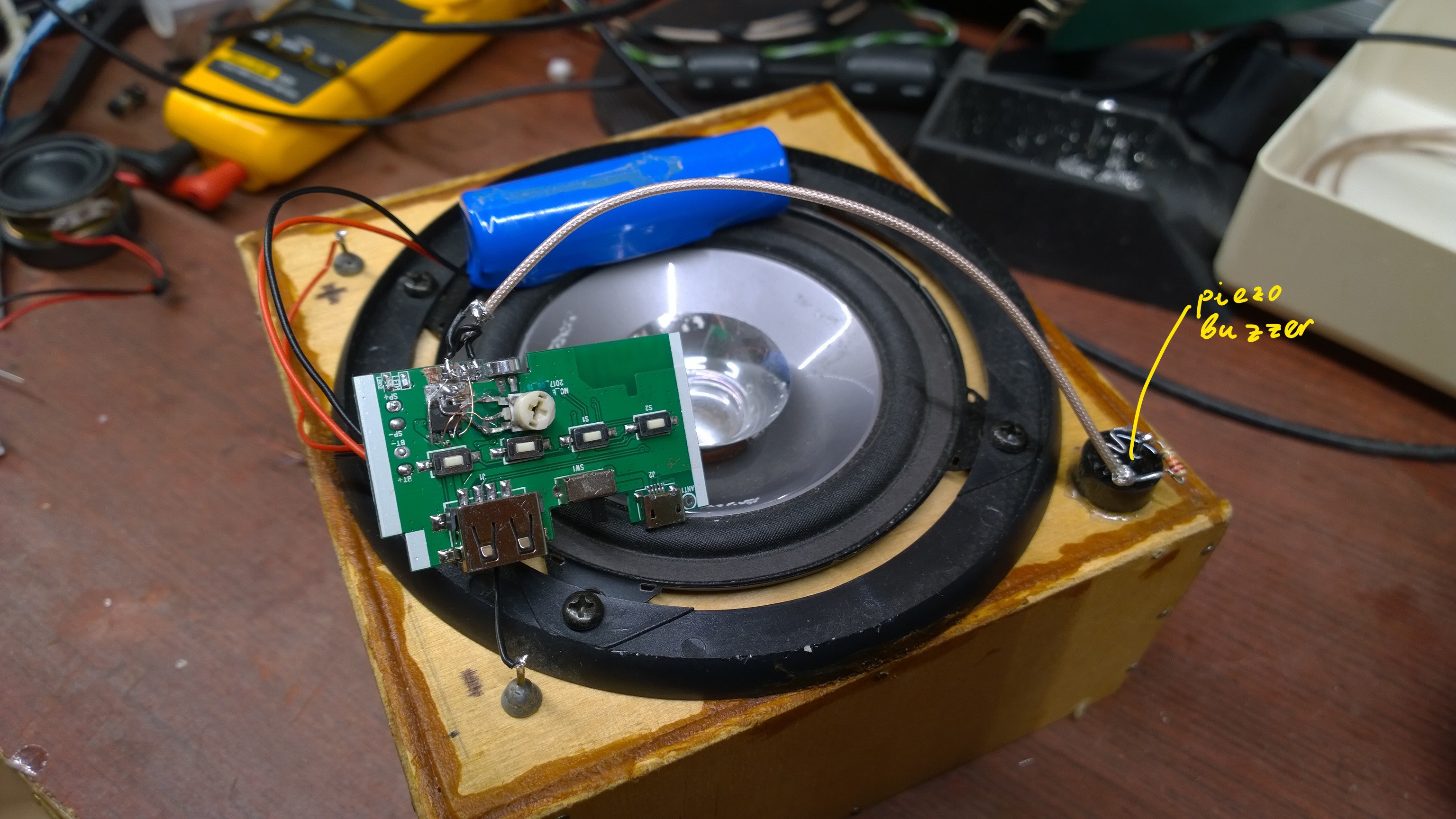
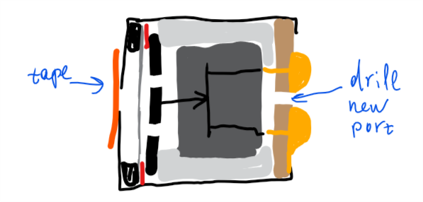
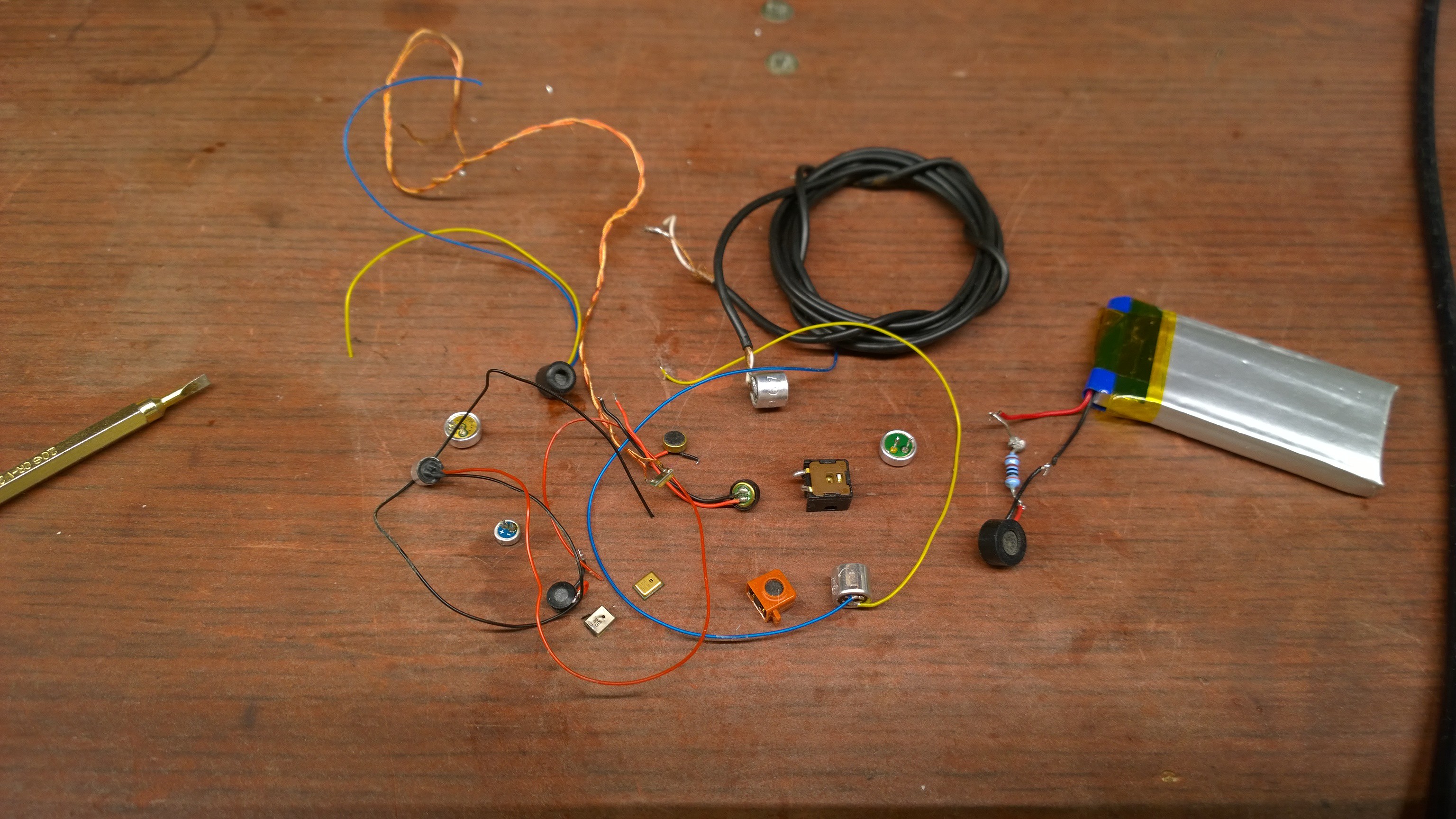
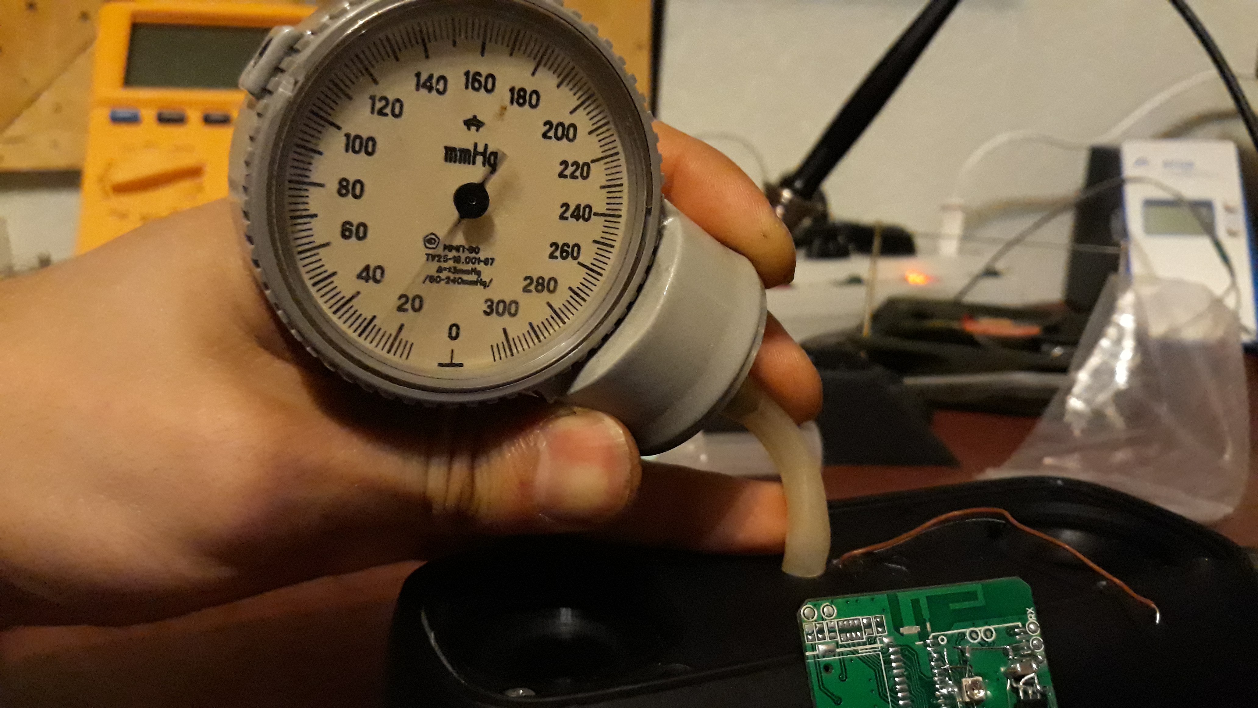
Not any microphone will do. The microphone should have very flat frequency response in bass range of interest, and perfect phase response as well. The microphone must also be able to handle high sound loudness, in my case it was 147 db (470 Pa of sound pressure, RMS). First I hacked a standard microphone to reduce its sensitivity and extend frequency response. It is tricky. Later I found out some piezoelectric buzzers do the job.

The enclosure must be well sealed. I'm not sure what will happen if it has passive subwoofer or a bass-reflex port. My system had a passive subwoofer originally, I have removed it.

The results are not exactly what I wanted, but it does give a good amount of pleasant deep bass. See frequency response change in project logs

KTK596.pdf

datasheet for a jfet in an electret microphone

Adobe Portable Document Format - 46.43 kB - 03/01/2018 at 16:52

Preview
Download

  • Piezo sounder makes a good microphone

    DeepSOIC05/11/2018 at 23:46 0 comments

    Modifying microphones is tricky. Very tricky. I was successful only ONCE, a few attempts after that success failed. Sometimes I would not get the proper sealing, sometimes I destroyed the fet, sometimes I was just sick of messing with these mics that are not designed to be taken apart. I need a better transducer, badly.

    Visited electronic component store. Bought a few piezo buzzers to test. Quick success!

    It is HPM14A. I took one apart to see what's inside. It has a sealed volume behind the metal-ceramic diaphragm. Works down to some extremely low frequencies.

    It puts out voltage proportional to flexing of the diaphragm. It looks like a 11 nF capacitor electrically, so the input impedance of the following amplifier must be a few megaohms. That's no problem, just make sure to use FET-input opamp.

    The output voltage amplitude is from 0.3 to 3.4 V depending on loudspeaker and volume, which is a very convenient magnitude to work with.

    The diaphragm is extremely thin btw. There is no chance of getting it off without cracking the ceramic, I'm afraid. But it looks like there is no need for that.

    I was anxious about its sharp resonances around 4 kHz. I expected the whole system to self-oscillate at that frequency. Well, it didn't, but there was a noticeable ring around there. A little bit of low-pass filtering in feedbass loop made it inaudible.

    The circuit:

    3M resistor, in combination with piezo capacitor and 6.8nF one set low frequency cut-off of the feedbass loop. 27K-6.8nF RC network is a low-pass filter, for reducing feedthrough of that buzzer resonance. That 6.8 nF cap also reduces buzzer's sensitivity to low frequencies by forming a capacitive voltage divider - this is not important for this particular implementation, but might come in handy if you can't set the gain low enough with the trimpot. 

    Trimpot adjusts the amount of positive feedback (tweak it until you get low-frequency self-oscillation, then back off a bit).

    Assembly, a total prototype quickly thrown together for testing.

    And the frequency response.

    As before, Feedbass hasn't completely rectified bass part of frequency response, but it reduced the fall-off rate significantly.

    There is a peculiar peak at around 2 kHz. I'm not sure where does it come from. Maybe the resonance of the buzzer has changed upon attachment to the speaker... maybe mechanical vibration is transferred through the case instead of air... But with ears, I don't notice it.

    Also, I'm quite surprised to find a 3rd-order fall-off in the low frequency. I expected a 2nd-order fall-off (I plotted a best-fit for that with a thin red line). Does anyone have any idea on why is it 3rd order? 

    And pyroelectricity does cause a bit of trouble (apparent DC offset) for a minute or so after soldering the buzzer, but then the offset just goes away.

  • Impressions

    DeepSOIC03/23/2018 at 19:51 0 comments

    I've been using my feedbass-equipped speaker for a little while, and I noticed two good things.

    ++ Good tradeoff between bass and loudness.

    If I were to extend frequency response down to say 50 hz perfectly, the speaker will only be ok at very low loudness, as a lot of bass boost is required (approximately 14 times). Feedbass makes only a 4.5 times boost, which seems to be enough to make the bass very audible, yet leaves much more room to increase the volume.

    ++ Good overload behavior

    As the amplifier clips, the positive feedback is broken, and the system almost instantly leaves the overload. In contrast, a pre-filter based design would remain overloaded until the transient is finished, letting no sound through for that period.

    This results in a very soft overload behavior of feedbass, where the bass is distorted, but the sound is not interrupted. With filter-based correction, as soon as some subtle overload begins, the music is completely ruined by the intermodulation. With feedbass, there is almost no intermodulation, and moderate overload sounds OK.

    That makes me reevaluate the results: the project is an EPIC SUCCESS!!!, even though it's a bit accidental. And I plan making a few more feedbass speakers soon!


  • Why?

    DeepSOIC03/08/2018 at 01:13 0 comments

    I've been asked by @charleslinquist , why not add bass boost for that particular speaker+box with a filter network in front of the amplifier, instead of all this mess with microphone? Nice question.

    I actually have been doing that for a long time, but using a digital processing instead of an analog filter. Building analog filter just seemed too much of an adventure, and here's why.

    With a sealed box, the frequency response depends directly on cone motion x(t). This motion can be reasonably well approximated with a mechanical oscillator equation:

    Where omega_0 is resonance frequency in rad/s, gamma is viscous friction coefficient and f(t) is external force (i.e. current through voice coil). Dampening by electromagnetic braking is not exactly equivalent to viscous friction, but should be good enough.
    Flat frequency response more-or-less corresponds to

    where a(t) is the waveform of audio record, i.e. air pressure vs time.

    So, we can solve for voice coil current:

    So easy. Just mix the signal with some first and second intergrals, and the response is compensated... and with perfect phase btw!.. Not so fast, of course. Now we have a problem, that the filter has infinite gain at DC, and we shouldn't amplify anything below 16 hz (because humans can't hear that stuff, while it would cause the speaker to work really hard). So we have to add some high-pass filtering. And in order to eliminate the infinity, the filter has at least to be of second order. My experience with digital filters shows that second order doesn't work well (still extreme sensitivity to subsonics in recordings), and third order is the way to go.

    So naiive filter would be: 

    This requires about 5 opamps for a straightforward design. Maybe this can be collapsed into fewer stages... for example, 2 orders of the subsonic can be embedded into integrators, by doing them as RC-filters rather than perfect integrators. Also, at least two trimpots in mixer to tweak to excellence.

    Now that is still not it. If I decide that my subsonic is 16 hz, my box with tiny speakers will be almost useless because of low maximum loudness possible... a bit more volume, and it clips horribly due to enormous bass content required to rectify the response. 

    So choosing the low frequency cut-off is a compromize: you can get deeper bass, but at an expense of loudness. 

    In my digital filters, I've exposed that subsonic cut-off frequency as adjustable. This way, if I am in silent room enjoying muskick, I make deeper bass. If party time and muskick has to be loud, I sacrifice bass depth.

    So in the analog filter, I want a pot that adjusts the corner frequency of the subsonic filter. And that takes a TRIPLE FREAKING POT! for one filter! And if stereo, a SIX-IN-ONE pot. Man, that's insane. Not to mention that the pot has to be used in rheostat mode, which makes it unreliable. Sure, that can be made with voltage-controlled attenuator ICs, but it's still waaaay too much trouble.

    So the design explodes into a horribly complex and hard to calculate system, with many opamps, trimpots, capacitors, and the at-least one triple pot.

    The beauty of feedbass idea is that the same resutls could be achieved with one simple frequency-independent signal path, and one single pot that adjusts the subsonic filter (or double, if two separate speakers). Isn't it beautiful?

    So far, as you can see in previos project log,  the idea doesn't quite work with the system I tried it on. I have some hopes for it if I use a current-drive amplifier instead of a typical voltage-drive one, but so far I have not seen any easy-to-power-from-single-lion-cell IC that will force current into speaker rather than voltage. 

    To summarize. 

    Filters in front of amplifier:

    * a number of opamps required

    * at least 2 trimpots

    * a triple potentiometer for low-frequency cut-off adjustment

    * lot...

    Read more »

  • The effect of feedbass, measured.

    DeepSOIC03/05/2018 at 20:23 0 comments

    So, I hoped to get something like this...

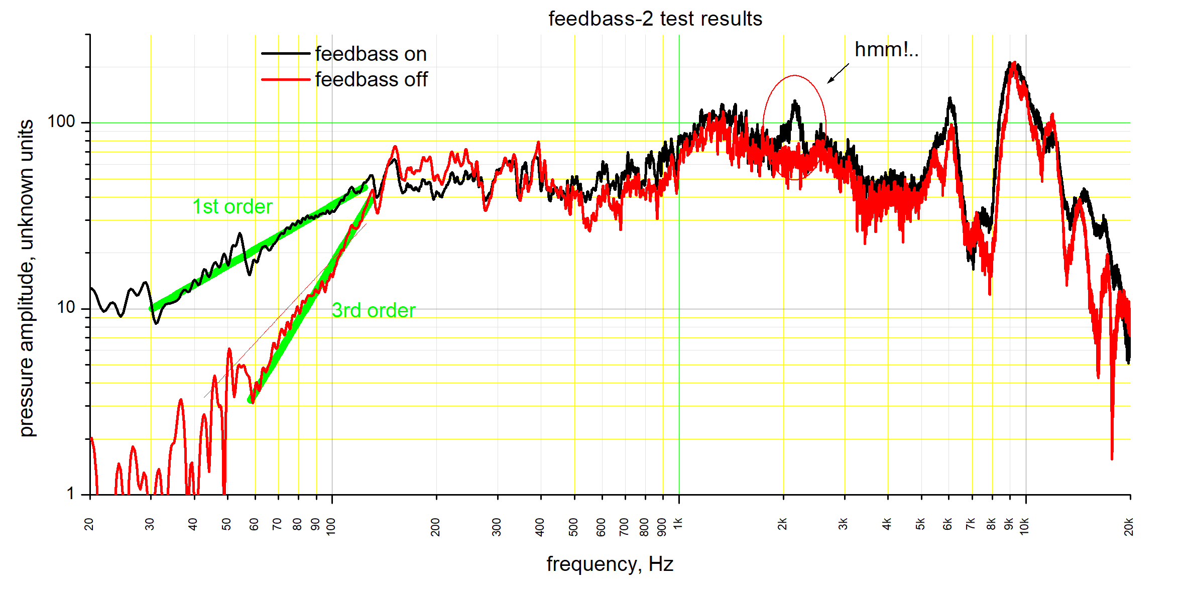
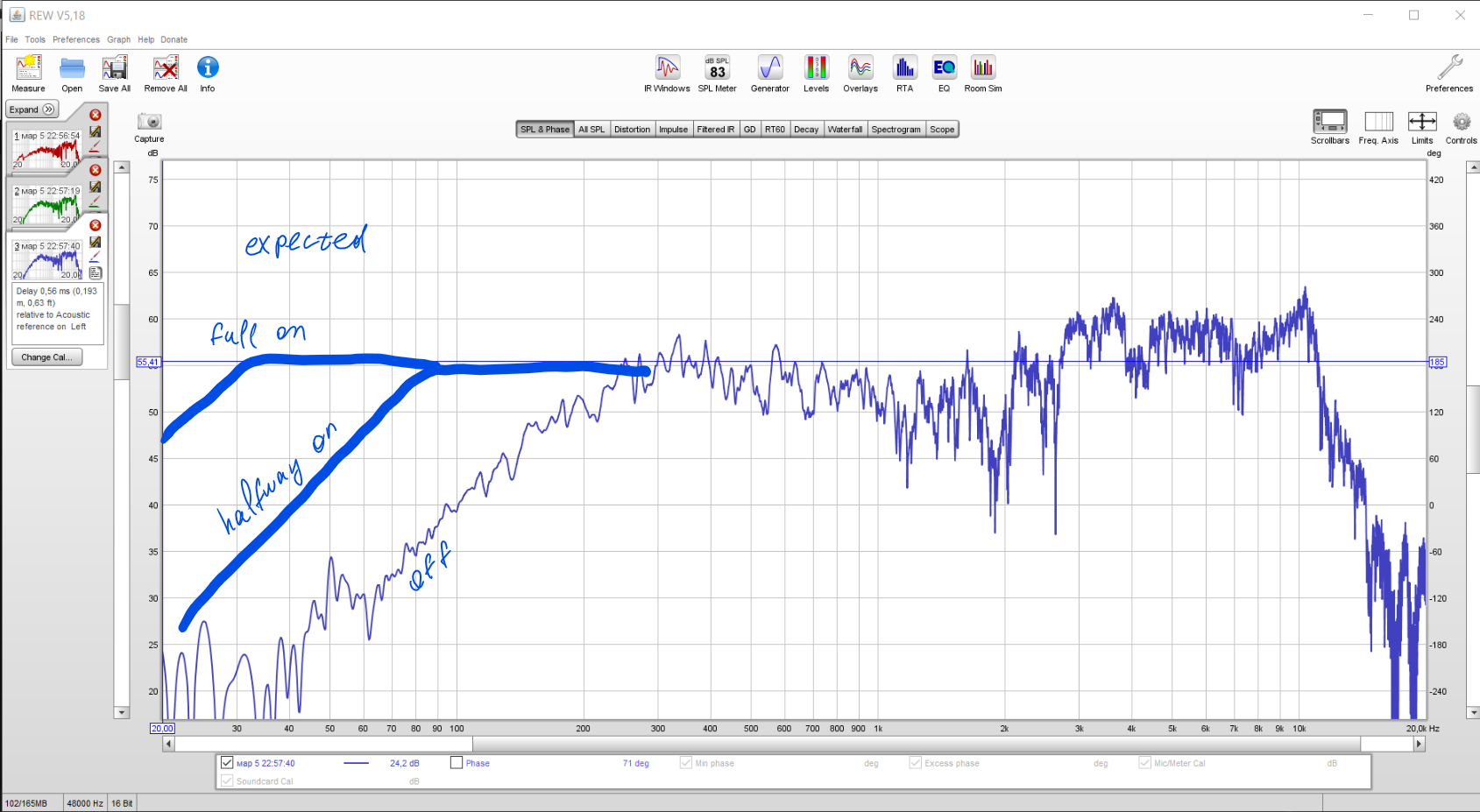
    And of course... it's not really what happens. This is what I measure:

    ("full on" means feedbass pot is at the point just below where self-oscillation begins)

    So. Does it work? well, NO. It does something different to what I wanted. But what it does do is it makes the sound of this little speaker much more massive. Not quite massive as in absolute, but relative to what it was, the improvement is pleasant and very noticeable.

    Now, why doesn't it do what I expected it to? well, there is a big thing, that I hoped would be small. When compensating for a spring, I need to put out Force. Force is proportional to current through voice coil. But the amplifier outputs voltage, and voltage is related to current as follows (ignoring coil's inductance):

    I = (U - U_backEMF) / R

    My original hope was that the drivers are crappy, and their back-emf is negligible, so output voltage and coil current are in direct relationship. However, as it is hinted by quite a few observations, U_backEMF, which is voltage generated by the coil due to its movement in magnetic field, is not negligible at all. One of the things that suggests it is the lack of resonance peak in frequency response. The resonance is dampened because the coil is essentially shorted by amplifier, and it brakes like a shorted DC motor. That resonance appears if I connect the speakers through 40 Ohm resistors. 

  • Finally, I have a microphone

    DeepSOIC03/05/2018 at 19:20 0 comments

    So, all my attempts at deafening a microphone without full teardown had failed, so I went for full teardown.

    This is what I did:

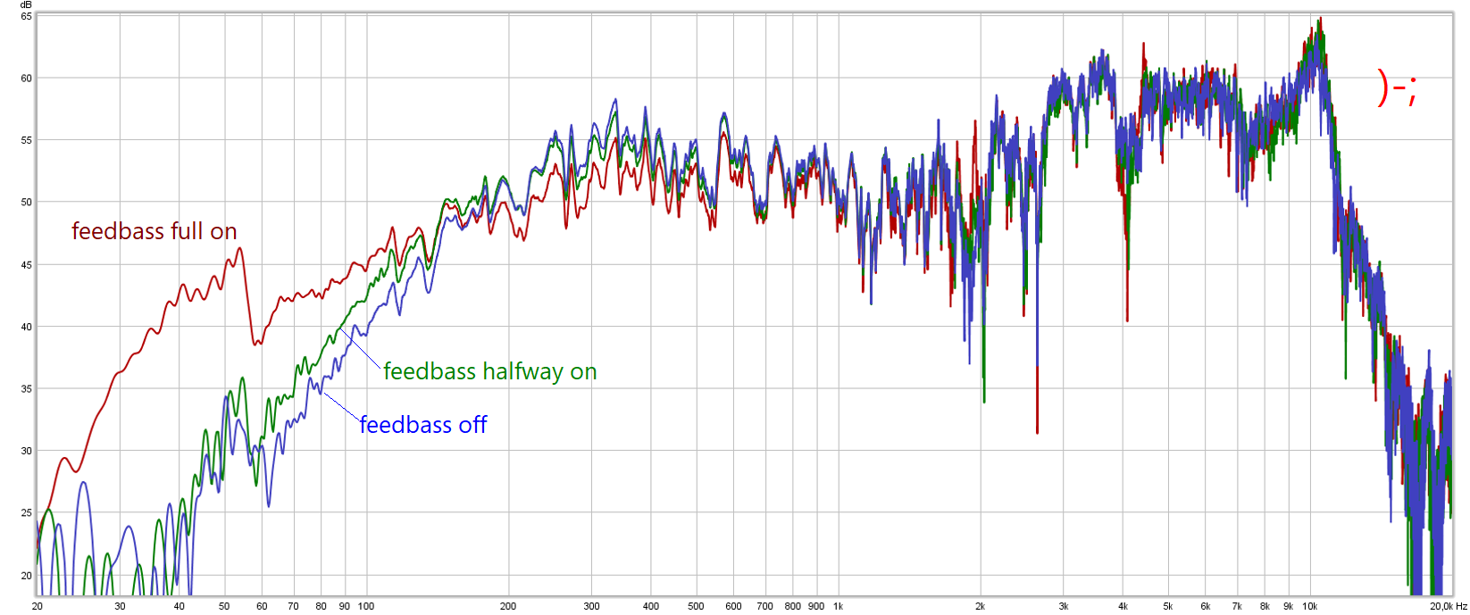
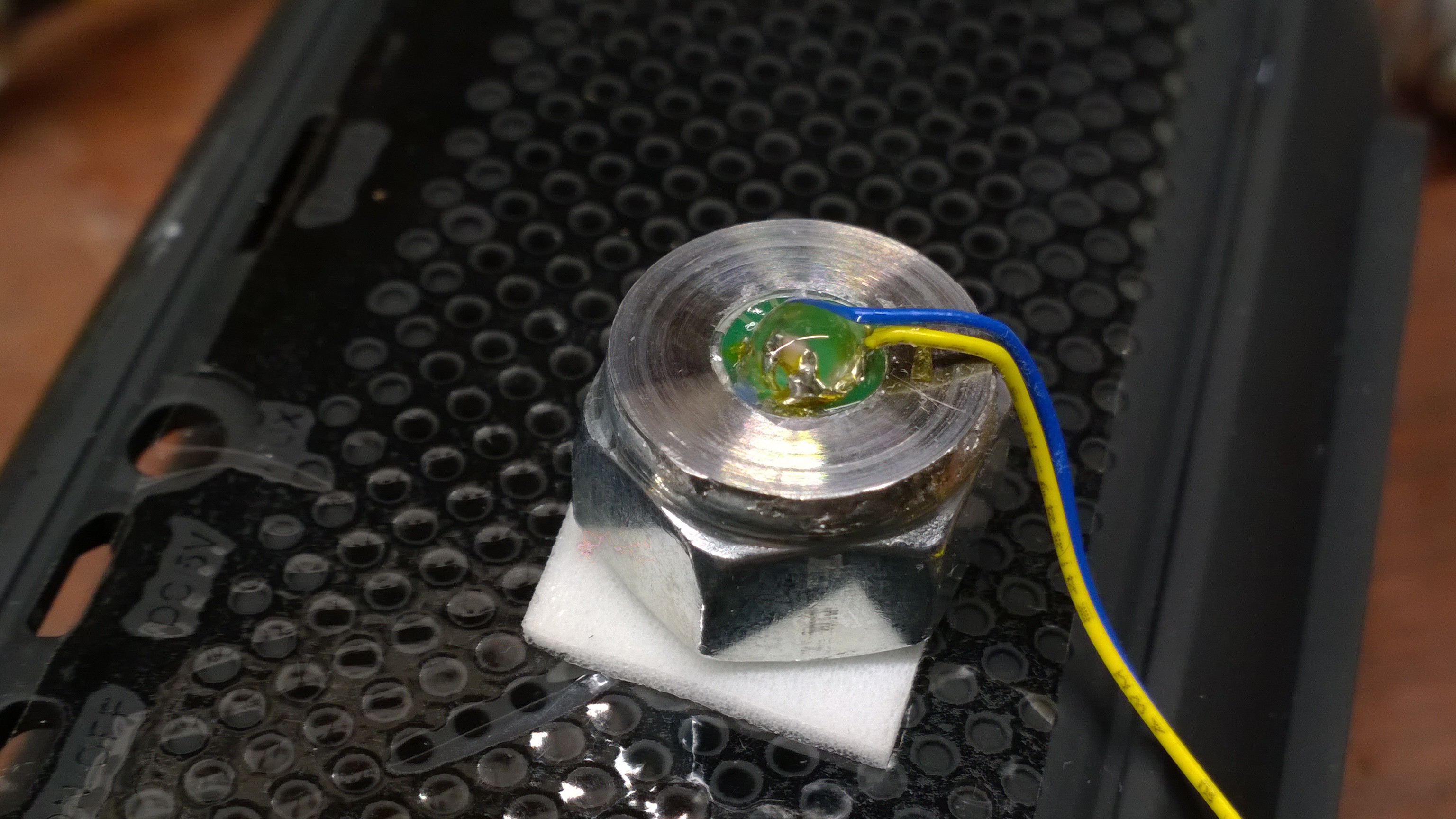
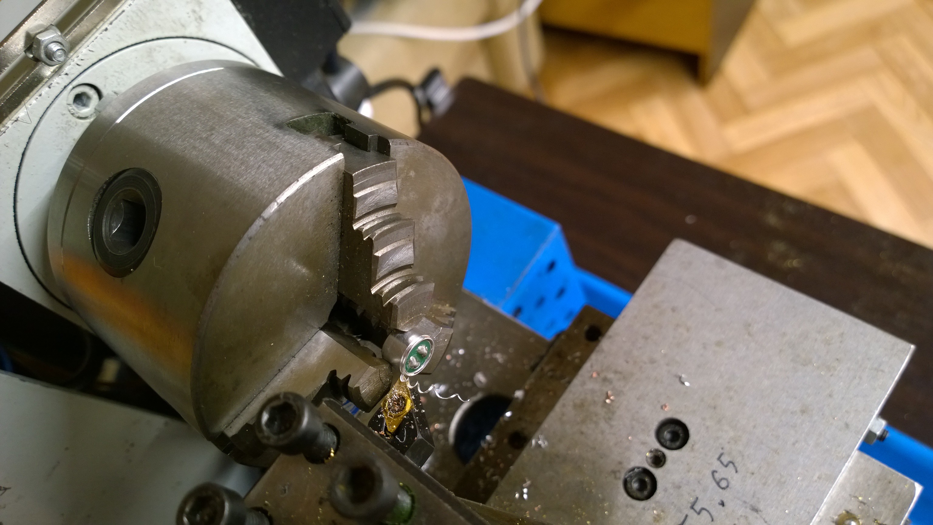
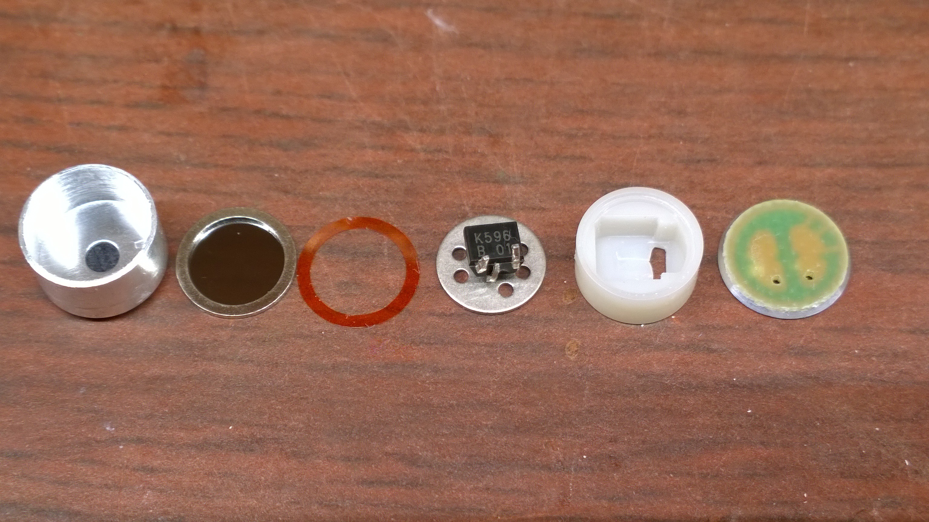
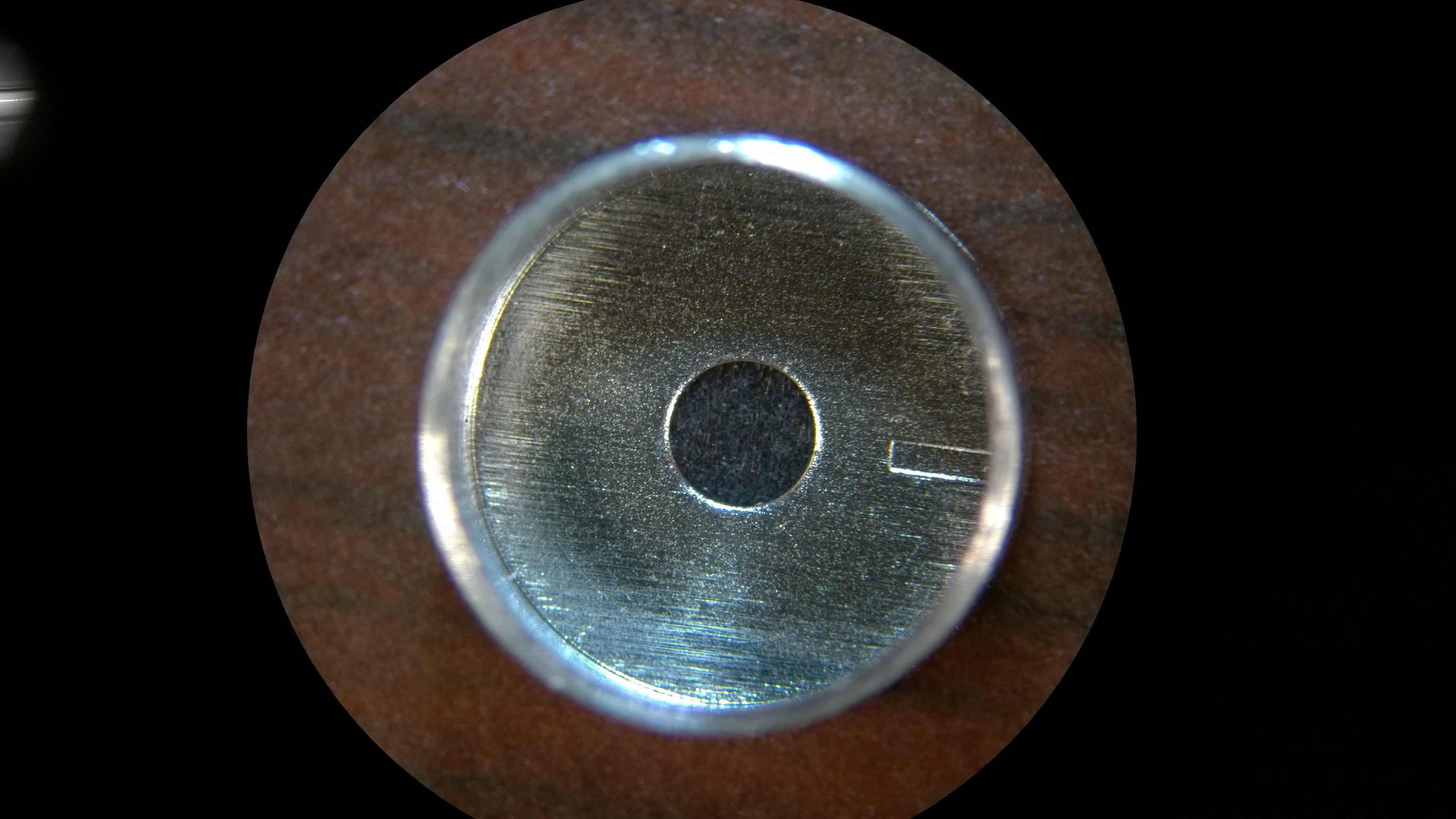
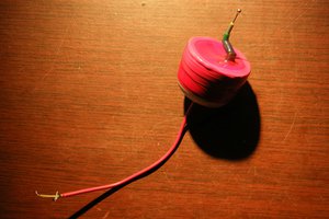
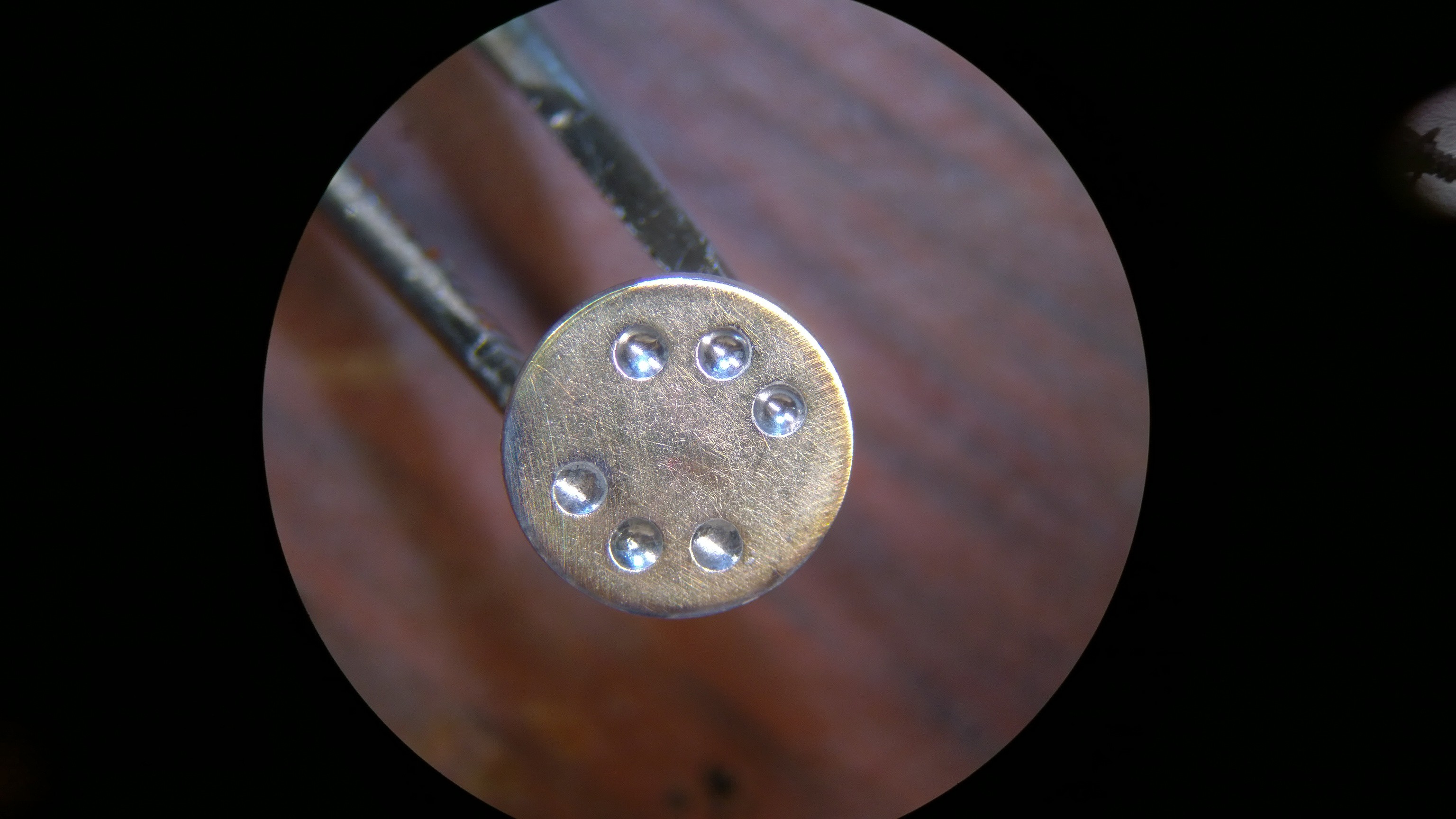
    And to put the microphone back together, I turned a capsule from a nut and a bolt:
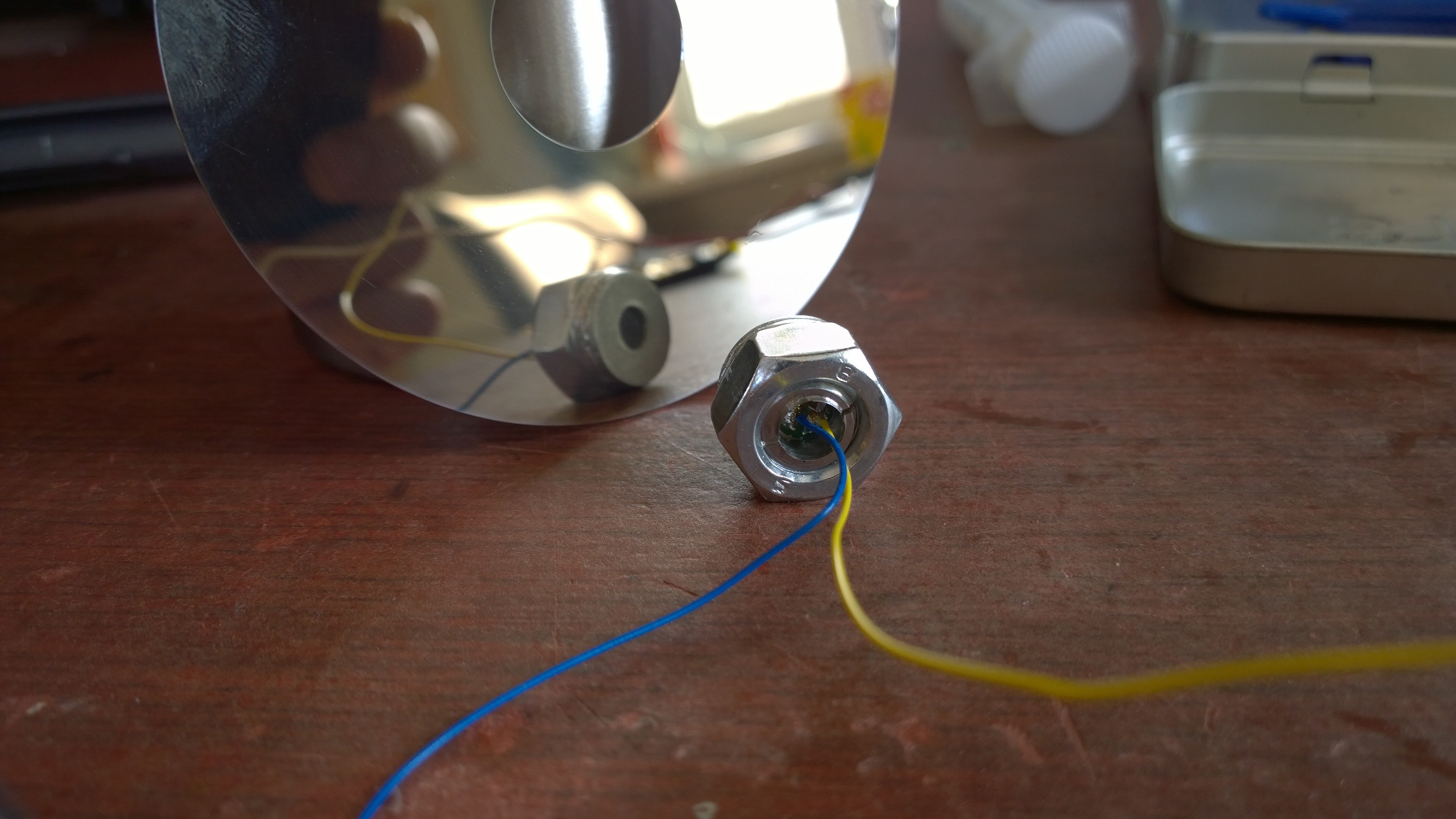
    So now I can easily take it apart and put it back together as many times as I like.

    This microphone works. But its response is too quick.

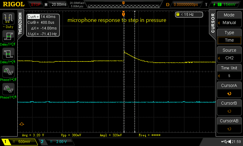
    And that is something that took me a long long time to figure out. Because I didn't go straight to testing step response. I just tested it at 40 Hz sine wave as before, verified that the sensitivity is just right, and went straight to making circuit. That circuit did do something, and the speaker was giving out some very nice sound. I assembled it into a nice portable thing, and took it with me the next day. To find out that outside, it went crazy and started to self-oscillate.

    Then I found out that it was extremely sensitive to temperature of the microphone. And only at that point I started measuring responses.

    The thing is, that response (its decay time) is very sensitive to temperature. It is very related to leakage currents of jfet, which depend exponentially on temperature. It is caused by the capacitor being discharged through the gate of JFET. I estimated that at room temperature, gate-to-source leakage resistance is about 20 GOhm, not 20 MOhm as was stated in the datasheet.

    So I needed a way to increase the response decay time at room temperature. 

    I achieved that by adding that feedback capacitor (15 pF) I initially wanted to, across jfet's gate and drain. That was a...

    ...Success!! (oops, I forgot to capture a screenshot!)

    See that capacitor inside the transparent blob of photocurable epoxy? I hope you do... I forgot to take a picture before putting the blob.

    So now I have my feedbass working more-or-less as I wanted to, and in the next project log, I will publish frequency responses of the speaker!

  • rant

    DeepSOIC03/03/2018 at 14:50 0 comments

    There is so much happening, I can't find time to write up project logs. The project is seriously ahead of the logs so far...

    I have the speaker with feedbass built, I tested it, it was great, but then I found weird temperature effects, and now it looks like it is not working as it was supposed to, and good sound was essentially a coincidence.

    Now, this is the latest stuff I found out.

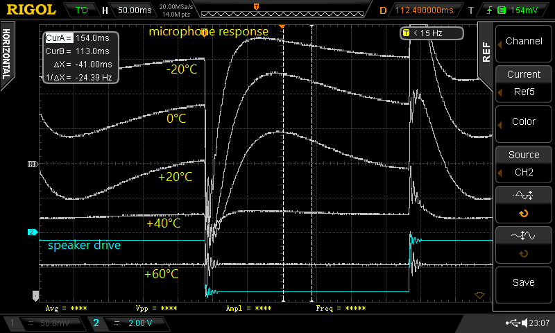
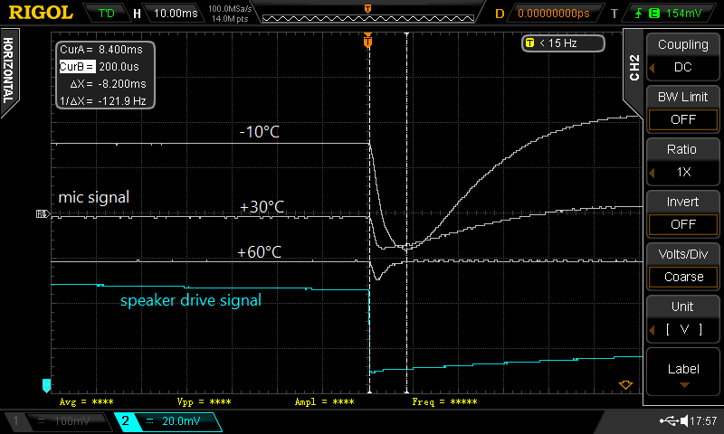
    That microphone response looks really weird...

  • Desensitizing a microphone. Failures.

    DeepSOIC03/02/2018 at 20:21 2 comments

    FAIL #1. feedback capacitor.

    First attempt was to add a capacitor between jfet drain and gate. This should add feedback, thus reduce the gain of the jfet.

    I was trying to do that by drilling holes in base pcb. (I didn't want to take the mic apart, because it's unclear how to put it back together after that, and if that may ruin the electret.)

    First microphone I drilled had gate electrode available right behind the pcb, so I soldered a capacitor, and plugged the hole with photocurable epoxy. Unfortunately, I likely had blown the jfet while drilling, likely because my dremel was not earthed... the microphone was dead.

    So I took another very similar looking one, drilled in same place, but there was no gate electrode. Then another one. I found where gate electrode was by illuminating the internals of the microphone with a laser, but when drilling it, I broke the thing, so another fail.

    At this point, I ordered a few kinds of microphones, so that I have a bunch of similar ones to play with. So far, every microphone I had was unique, and its internal structure was quite unpredictable.


    FAIL #2. changing internal volume.

    If I reduce the internal volume of the microphone, I increase the stiffness of air inside, reducing the deflection of diaphragm. And I figured a really really easy way of doing it: plug the sound port with tape, and make a new sound port by drilling a hole in back PCB. 

    Done... and .... it's not enough! Still clips severely. =(


    FAIL #3. depolarizing electret with temperature.

    Easy, I just touched the microphone with soldering iron for half a minute or so. As the microphone cooled down, it was still waaay too sensitive, and I did notice substantial distortion at low SPL, so I might have melted the diaphragm, or something else was damaged.


    FAIL #4. Compensating electret with external voltage.

    If I cut pcb traces that connect the case to one of the pads on the back PCB, I can then put a voltage source in series with microphone's sensing capacitor. 

    So I did it, and applied up to 100 V in either polarity. That was not enough deafen the microphone. It may be possible with higher voltage... but I don't want to mess with building a high voltage source just for that, and I need to compensate the field so that only about 1% of it remains, which requires a really stable voltage source, and precision tweaking with tongue at the right angle, and may drift with temperature, so that's not an option. Out of curiosity, it would still be interesting to check, how much voltage is embedded into the microphone thanks to the electret....


    Other ideas that I didn't try:

    * depolarize electret with x-rays

    * with same approach as in FAIL 2, fill the cavity with something (say, oil) before taping it shut

    * mechanical shielding from sound pressure. The difficulty is ensuring frequency response stays flat in 10-300 hz range, and has no phase lag...

    * and of course, a lot more ways requiring a full teardown.

  • teardown of an electret microphone

    DeepSOIC03/01/2018 at 17:18 0 comments

    Let's take one apart, to see how it works, and how can we make it deafer.

    Left to right: outer shell, diaphragm stretched on metal ring, a spacer ring that sets capacitor plate separation, fixed plate of capacitor with jfet (datasheet) spot-welded to it, another spacer, and back PCB.

    There is a small indent on the outer shell, which likely is the leakage path for air, to slowly equalize pressures inside and outside of the microphone.

    Here, I doodled a cross-section view, and a schematic.

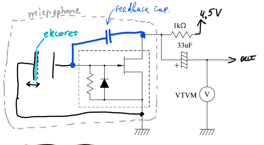
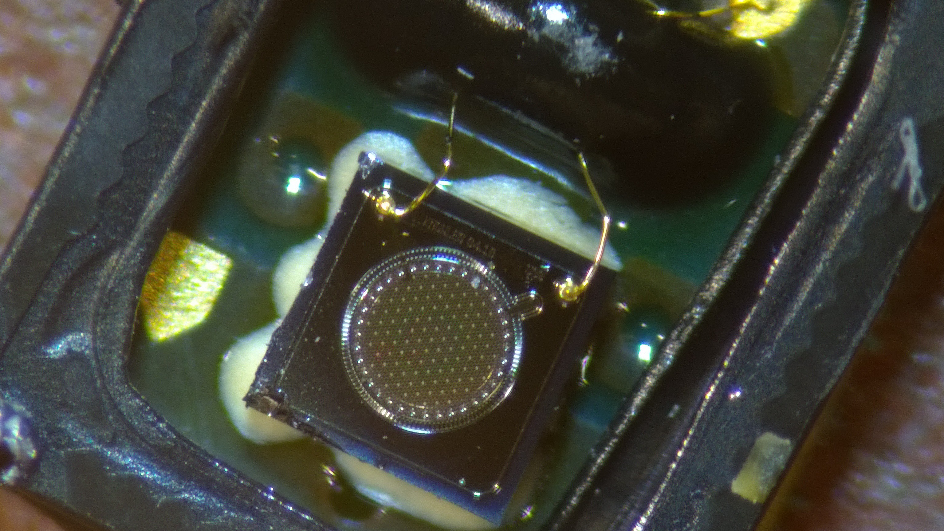
    As the sound wave passes by, it changes the air pressure outside of the microphone. The difference in pressures between outside and inside causes the diaphragm to bow, until the pressures are equalized (assuming the diaphragm is very flexible). The capacitor's capacitance changes, and because of the built-in electric field thanks to electret, some voltage appears on the capacitor. That change is amplified by the jfet.
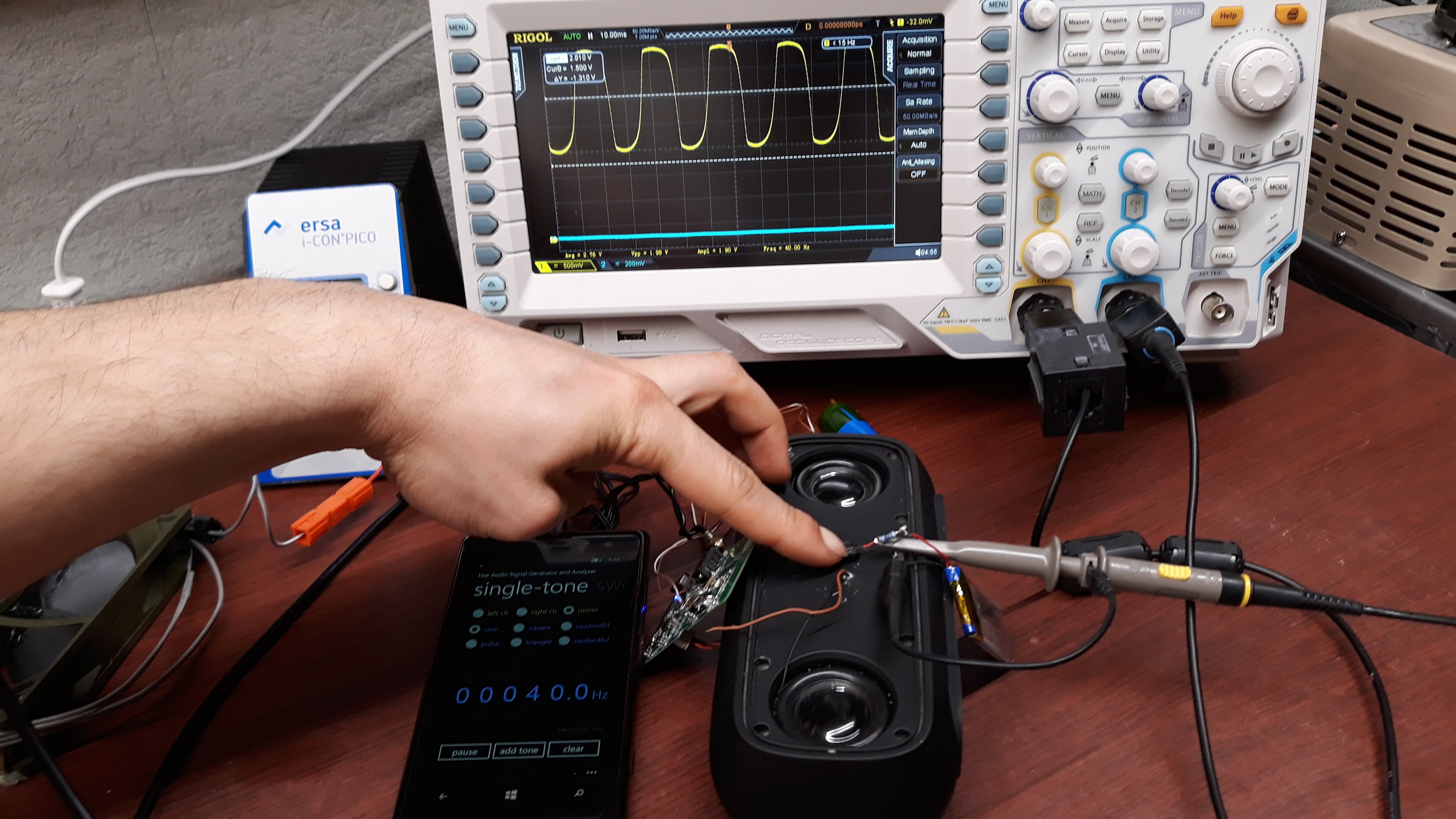
    Note that other microphones may have somewhat different geometry of elements, but the basic principle should be the same.

  • Microphones...

    DeepSOIC03/01/2018 at 01:23 0 comments

    There should be plenty of sound in cabinet... I shouldn't worry about noise too much, so the choice of a microphone should be fairly easy...


    Oops, it overloads. I tried a few more...


    including a couple of these new fancy mems ones...


    and the story was the same. They all were in gross overload.
    After taking apart almost everything around that had a microphone inside, I gave up, and went googling. Turns out, it's not very often that manufacturers specify the overload SPL, and even worse, I don't know, what SPL to shoot for. Oh wait. If SPL is so high, maybe I can measure it,,, with a MANOMETER? OK, let's do it...


    So it's 10 Torr peak-to-peak. which is 3.53 Torr rms, which is 470 Pa rms -> 147 dB spl. The maximum overload spl for the mics I digged so far was 136 db.. way not enough!
    So, two options remain. Keep searching for a low sensitivity microphone, or hack one to reduce its sensitivity. Sure, I picked the HACK WAY.


View all 9 project logs

  • 1
    solder the circuit

    I don't remember, what exact opamp I used, but it was made of pure obscurium. MCP6283 is a good replacement. If you need a higher voltage amplifier (for +-15V supply), LF356 is an okay choice. The only real requirement is that the opamp should have low bias current to create no significant dc voltage across 3M resistor.

    The trimpot can have any value from about 1K up to about 100 K. The lower the value - the lower the extra noise.

    LTK8002 can be replaced with any similar audio amp. Examples are mix2037 (excellent, but unobtainium), NAU82011WG (unobtainium), tpa6211, lm4871

  • 2
    attach the microphone to speaker enclosure

    The enclosure should be seriously airtight for best results. I recommend adding vibration isolation between the mic and the case to prevent unwanted mechanical coupling to the speaker through walls.

  • 3
    Power up the circuit, and tune feedbass.

    The speaker should respond to tapping, but not oscillate too much.

    Here's a video. Sorry, it's in Russian... but I've added English subtitles, use them.

    And it's done!

View all 3 instructions

Enjoy this project?

Share

Discussions

DeepSOIC wrote 03/09/2018 at 13:20 point

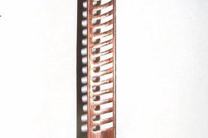
Thank you all for comments. Thanks to you, I added keywords "positional feedback" and "motional feedback", and now I can google up a lot of patents and some info on the subject. Before that, I couldn't find anything at all.

  Are you sure? yes | no

gtd wrote 03/08/2018 at 09:51 point

The Philips box was the 22AH587 (for instance).  But why you want to rely on mics? Sound is slow, weak and compressible, you will have to mess around with inertias, resonances and acoustical drop-ins and limitations. You can better use light (laser, UV, IR are no problem anymore) or capacities instead. We started 30 years ago using LEDs mirrors and LCRs .

  Are you sure? yes | no

DeepSOIC wrote 03/09/2018 at 13:18 point

light is great, but it's hard. It requires me to take the driver apart, attach the position detector somehow, put it back together. There is a good chance I will affect high-frequency performance (the drivers are full-range). It requires special approach for each different driver.

Using the microphone is easy... and that's the main reason. Well, easy, if only I could get the right microphone off-the-shelf, which I couldn't so far...

  Are you sure? yes | no

charleslinquist wrote 03/08/2018 at 01:22 point

I was involved in a motional feedback design 20+ years ago.  It was all-analog at that time.  A LED  was placed inside the cabinet and fed a fiber-optic bundle that was threaded through the vent hole in the center of the magnet and pole piece.   A phototransistor was located in the middle of the dust cap, and litz wire connected to it.  The phototransistor measured the light levels, which depended on the excursion.  That signal went through an analog squaring circuit that linearized the inverse-square value of the reflected light.  That signal was fed through a minimum phase active low-pass and was used as  feedback. It was very difficult to correctly position everything, but in the end it worked pretty well. And it is patented. A working system still exists in Ames, Iowa.

  Are you sure? yes | no

DeepSOIC wrote 03/08/2018 at 01:53 point

I once made experiments sensing cone position by utilizing back-emf from the voice coil itself. I ended up with an amplifier that can spin brushless motors with just one coil connected, that was pretty fun. The sensing didn't quite work though.

  Are you sure? yes | no

charleslinquist wrote 03/08/2018 at 02:25 point

I still think you would be ahead using an underdamped high-pass filter to feed the amplifier. It could add 12dB or so just below resonance and then roll off really fast below that.

  Are you sure? yes | no

charleslinquist wrote 03/07/2018 at 20:51 point

Since you need only a narrow frequency range, couldn't you use a dynamic (magnet + coil) microphone instead of an electret type?  

  Are you sure? yes | no

DeepSOIC wrote 03/07/2018 at 21:11 point

Dynamic mics are unlikely to have a flat frequency response in the range of interest (20 - 300 Hz). The flat frequency response is essential.


What I am slowly looking into is hacking a piezo buzzer disc to become a microphone. Looks very promising so far. However, I feel that my electret microphone was good enough, I tested the idea, and since it doesn't quite work, I'm losing interest to continuing the project.

  Are you sure? yes | no

charleslinquist wrote 03/07/2018 at 21:52 point

Good ones aren't down much more than 12dB at 25Hz, and you can use an R/C network to flatten that, since the curves I have seen indicate they roll off at about 6dB/octave.  Of course, there will be some phase shift...

The net effect of your mic + amplifier network will be to give bass boost.  And It seems that your goal is to automatically compensate for most any combination of box + speaker,  but if you have a specific speaker + box combination, why not just add the desired amount of bass boost with an underdamped high-pass network? That would accomplish two goals - extend the bass and also cut power at really low frequencies where the driver could either burn out (due to excessive bass boost) or rip itself to shreds because of too much Xmax.

Or, if you want to be fancy, why not add a motional feedback element (optical maybe?)  If you could linearize the sensor,  you could start adding feedback below 200Hz or so, and the feedback could increase the drive level at the required 12dB/octave below resonance.

 And finally, I think your microphone scheme would be quite confused if the box was ported.  

  Are you sure? yes | no

DeepSOIC wrote 03/08/2018 at 00:02 point

RC network to compensate a microphone... precise values and precise knowledge or trimmers required, all so very tricky... And as you pointed out, why not compensate for the whole boombox instead.

I've been doing the box+speaker frequency response correction with digital processing for a long long time now. Explaining why I don't want to use an analog filter for that is long, I'd rather write a project log. 

The feedbass idea seemed like an opportunity to greatly simplify and cheapify that compensation, so that I can make quite a few amp boxes with little effort.

  Are you sure? yes | no

DeepSOIC wrote 03/08/2018 at 00:48 point

And what would happen if the box is ported (or, more likely, has a passive subwoofer, which this box actually had originally), I don't know. That may be interesting to try.

  Are you sure? yes | no

rafununu wrote 03/01/2018 at 12:05 point

Philips made the same in 1975 for HiFi devices ! Due to treatment time, it can only work with low frequencies but as said someone, you will not make a donkey a horse !

  Are you sure? yes | no

DeepSOIC wrote 03/01/2018 at 16:01 point

interesting. Could you give more pointers?

  Are you sure? yes | no

Similar Projects

Does this project spark your interest?

Become a member to follow this project and never miss any updates