 DeepSOIC
Modifying microphones is tricky. Very tricky. I was successful only ONCE, a few attempts after that success failed. Sometimes I would not get the proper sealing, sometimes I destroyed the fet, sometimes I was just sick of messing with these mics that are not designed to be taken apart. I need a better transducer, badly.
Visited electronic component store. Bought a few piezo buzzers to test. Quick success!
It is HPM14A. I took one apart to see what's inside. It has a sealed volume behind the metal-ceramic diaphragm. Works down to some extremely low frequencies.
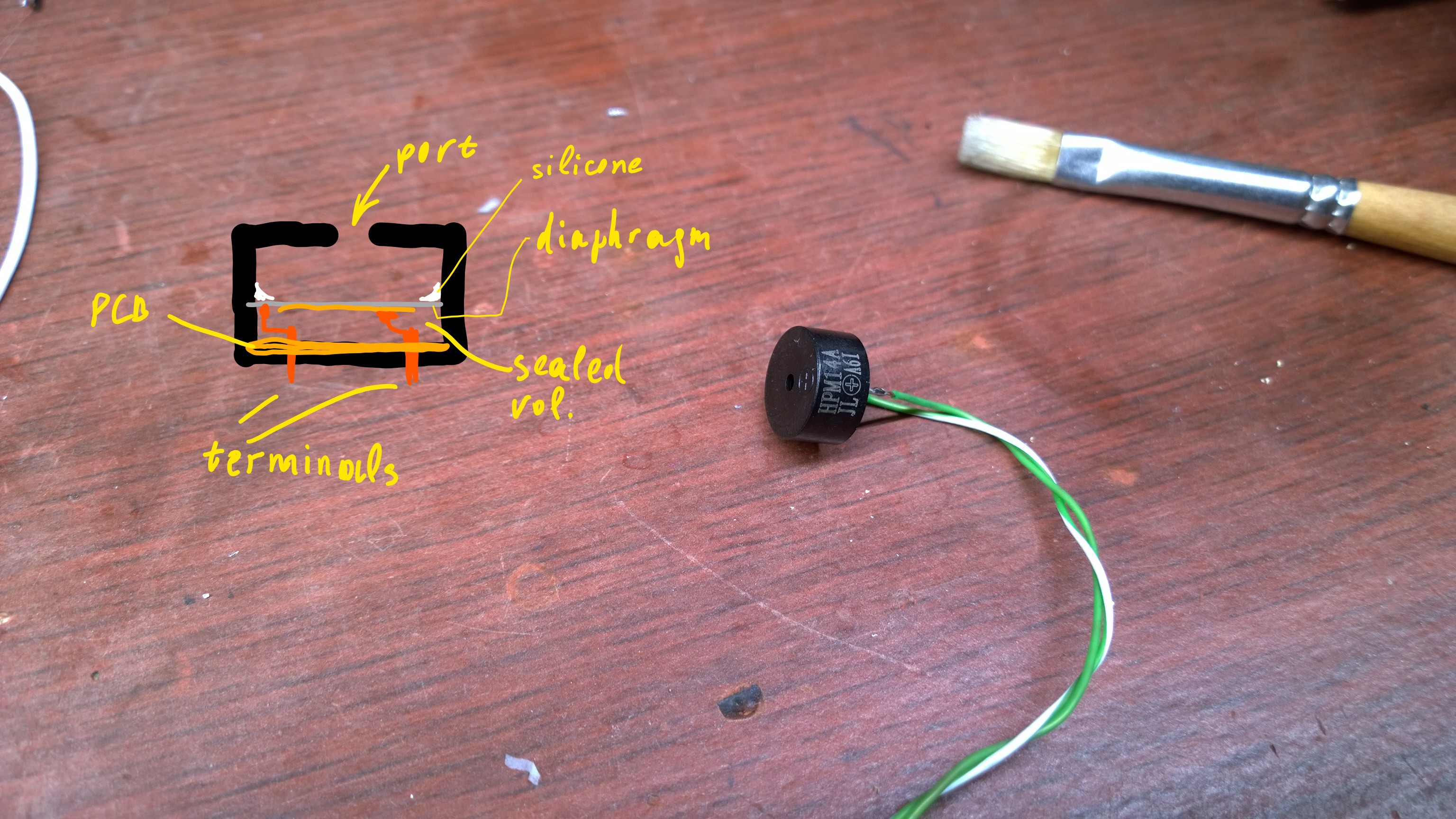
It puts out voltage proportional to flexing of the diaphragm. It looks like a 11 nF capacitor electrically, so the input impedance of the following amplifier must be a few megaohms. That's no problem, just make sure to use FET-input opamp.
The output voltage amplitude is from 0.3 to 3.4 V depending on loudspeaker and volume, which is a very convenient magnitude to work with.
The diaphragm is extremely thin btw. There is no chance of getting it off without cracking the ceramic, I'm afraid. But it looks like there is no need for that.
I was anxious about its sharp resonances around 4 kHz. I expected the whole system to self-oscillate at that frequency. Well, it didn't, but there was a noticeable ring around there. A little bit of low-pass filtering in feedbass loop made it inaudible.
The circuit:
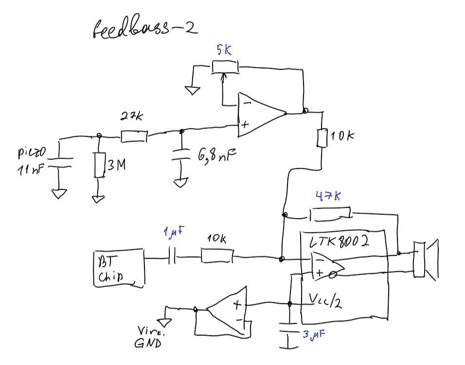
3M resistor, in combination with piezo capacitor and 6.8nF one set low frequency cut-off of the feedbass loop. 27K-6.8nF RC network is a low-pass filter, for reducing feedthrough of that buzzer resonance. That 6.8 nF cap also reduces buzzer's sensitivity to low frequencies by forming a capacitive voltage divider - this is not important for this particular implementation, but might come in handy if you can't set the gain low enough with the trimpot.
Trimpot adjusts the amount of positive feedback (tweak it until you get low-frequency self-oscillation, then back off a bit).
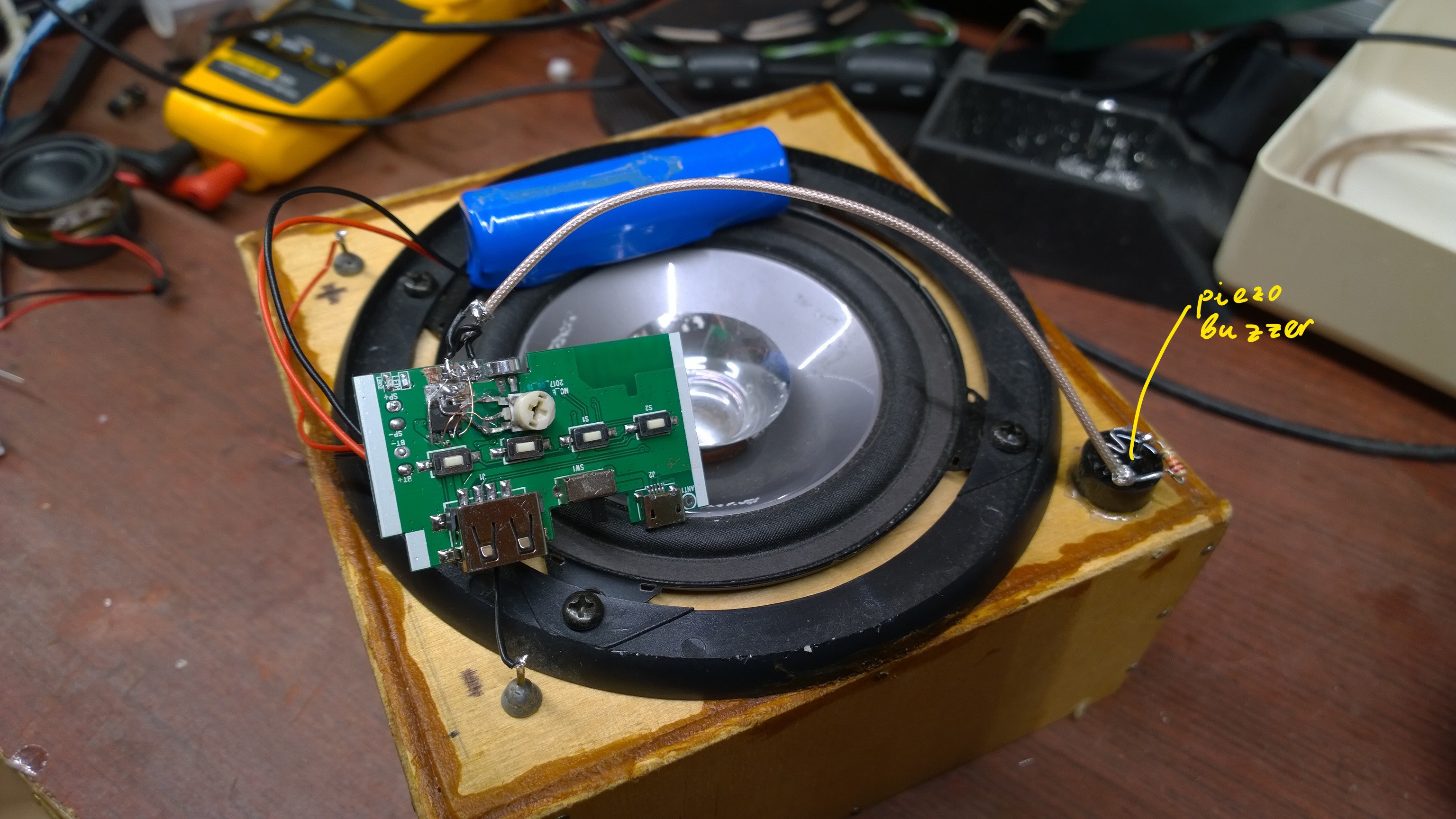
Assembly, a total prototype quickly thrown together for testing.
And the frequency response.
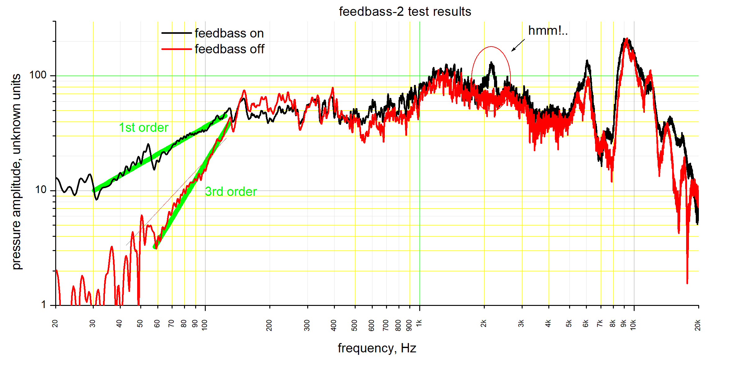
As before, Feedbass hasn't completely rectified bass part of frequency response, but it reduced the fall-off rate significantly.
There is a peculiar peak at around 2 kHz. I'm not sure where does it come from. Maybe the resonance of the buzzer has changed upon attachment to the speaker... maybe mechanical vibration is transferred through the case instead of air... But with ears, I don't notice it.
Also, I'm quite surprised to find a 3rd-order fall-off in the low frequency. I expected a 2nd-order fall-off (I plotted a best-fit for that with a thin red line). Does anyone have any idea on why is it 3rd order?
And pyroelectricity does cause a bit of trouble (apparent DC offset) for a minute or so after soldering the buzzer, but then the offset just goes away.
Discussions
Become a Hackaday.io Member
Create an account to leave a comment. Already have an account? Log In.