Close
0%
0%

Sol BLE Tracker

Solar powered Bluetooth Low Energy Tracker with beeper and LED to assist in locating it.

Similar projects worth following
The core of this project is a flexible PCB with a Bluetooth Low Energy radio that acts as a beacon with a beeper and LED to help locate it activated remotely from a cellphone. This circuit board is planned to be packed into 2 forms. The first a collar. Using flexible solar panels and Lithium Ion batteries it can be made to fit into a normal cat collar sized footprint. The battery should last a month without recharge and with only 15 minutes of light a day stay running permanently. Alternately it will be folded into a quarter sized tag that can be hung from a cat collar or keys or some other item to be tracked.

It was around January this year when my sister couldn't find her kitty. My dad was unconcerned and sure the cat was some where in the house by my sister wasn't. We ended up walking around the neighborhood for 2 hours looking for the cat only to come back home and find her under one of the beds. That was when I got the Idea to keep track of the cats with Bluetooth on their collars.

Kitty I had to search for outside for 2 hours even though she was just hidding under a bed.


By combining solar power with a tiny lithium battery and a buzzer and LED as well as a Bluetooth Low energy radio I figured I could immediately know if the cat was in the vicinity as well as be alerted if it left the area. The buzzer and LED would allow for easier location of the cat and the Solar Panel would get rid of the hassle of having to change/charge the battery of the collar.

Japer evades detection by pretending to be laundry, but with his new collar resistance is futile.

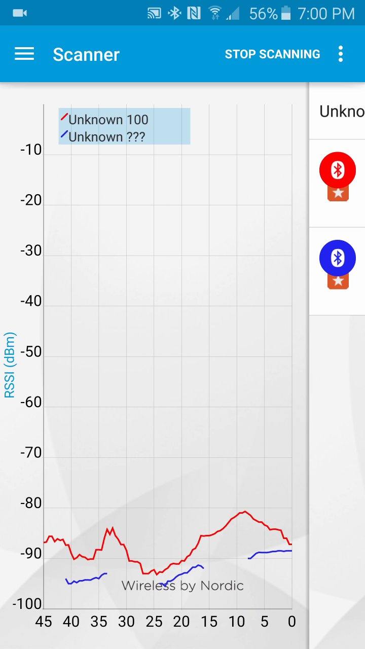
There are quite a few bluetooth trackers on the market however there are none that I can find that combine energy harvesting from the environment as well as the ability to audibly indicate their location. If you haven't tried it before its very hard to track down a bluetooth beacon with nothing more than an RSSI value.

Now for a breakdown of why parts where selected and expected performance.

It took a considerable number of hours to select the chips. Power consumption was the paramount concern with size as the next most important.

The solar charge control chip (BQ25504RGTT) with its quiescent current of less than 330 nA was the obvious choice.

The selection of the BLE121LR-A-M256K was driven primarily by the BGScript language. This removed the need for a secondary controller, with its low power consumption, 8dBm output power, and pulse width modulation capability to drive the buzzer it came out ontop.

Because I needed to use LiPo chemistry to have enough current to drive the beeper I needed a LDO to regulate the voltage below the BLE Modules 3.9 maximum input voltage. The TPS78330DDCR was chosen for its 500nA quiescent current.

The buzzer (SMT-0440-S-R) was chosen to be as small as possible while being lound enough to here from a a couple rooms away, as well as drawing an amount of current drivable from a small LiPo.The buzzer (SMT-0440-S-R) was chosen to be as small as possible while being loud enough to here from a a couple rooms away, as well as drawing an amount of current drivable from a small LiPo.

The battery protection/charge chip (LTC4071) was picked because of its extremly low 550nA operating current and exceptional shutdown current 0.1nA!!! Unfortunately because of its low 60mA max current I have to bypass it and wire the buzzer directly to the battery but the transistor driving the buzzer only has a leakage current of 10nA so it isn't a deal breaker for a battery undervoltage condition.

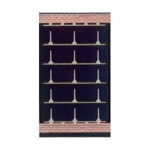
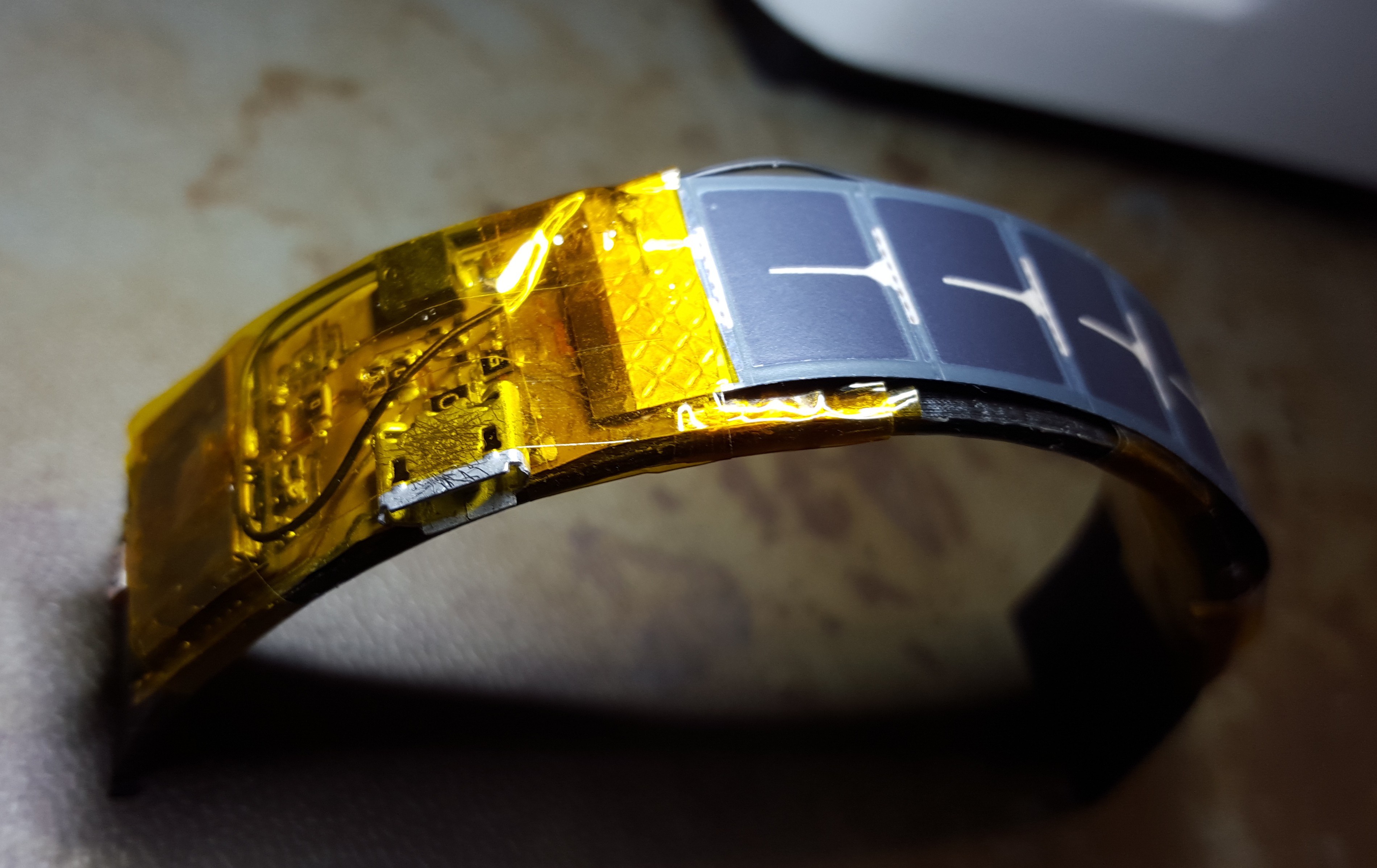
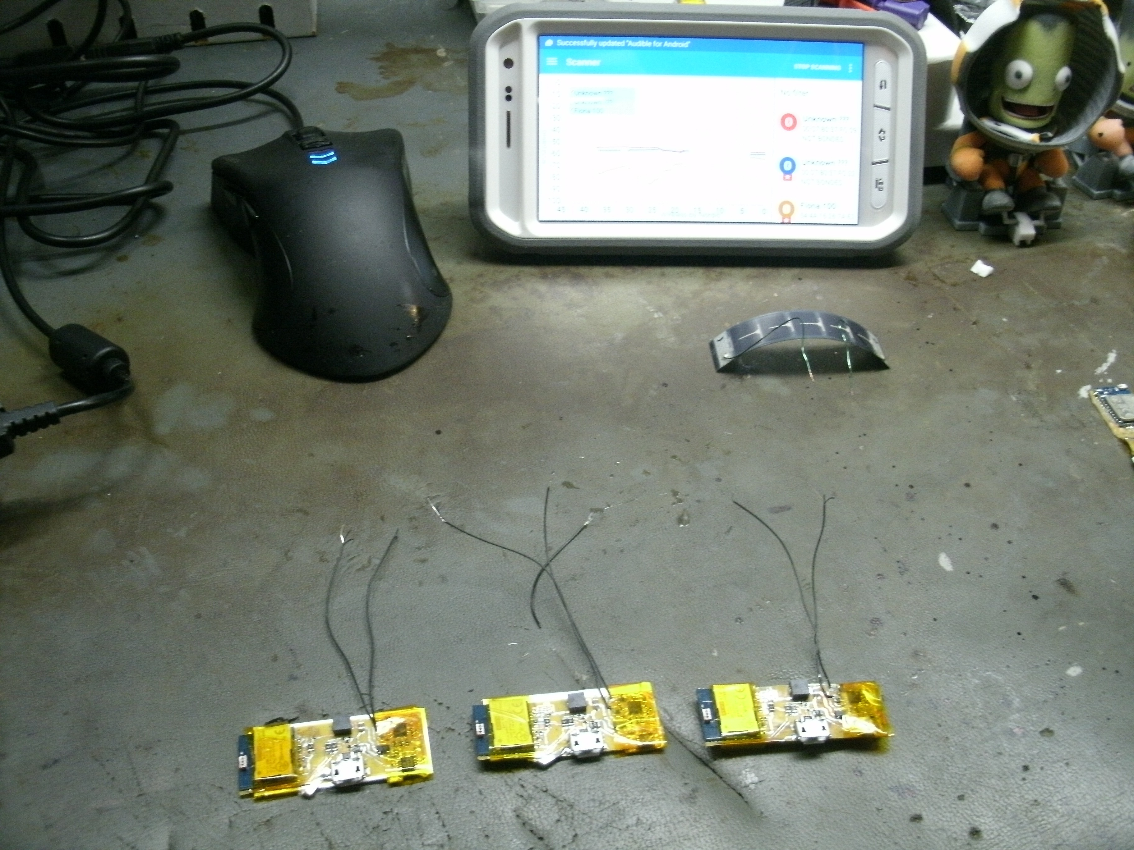
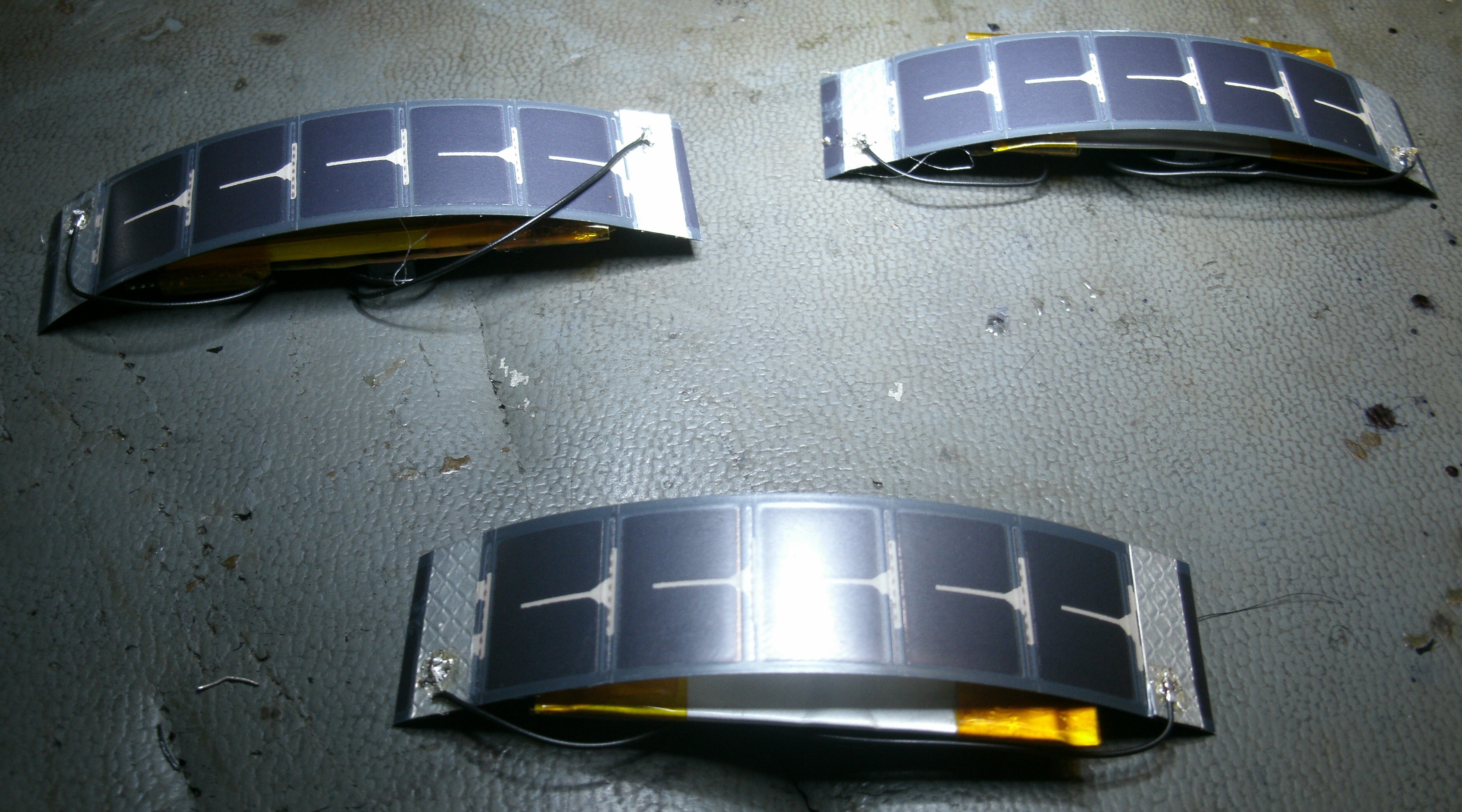
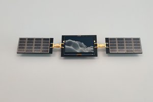
The Flexible solar cell was one of the harder components to source. It was hard to obtain the smallest size flexible solar cell in limited quantity. Ultimately I had to resort to EBay. The SP3-12 was selected because it was narrow and flexible.

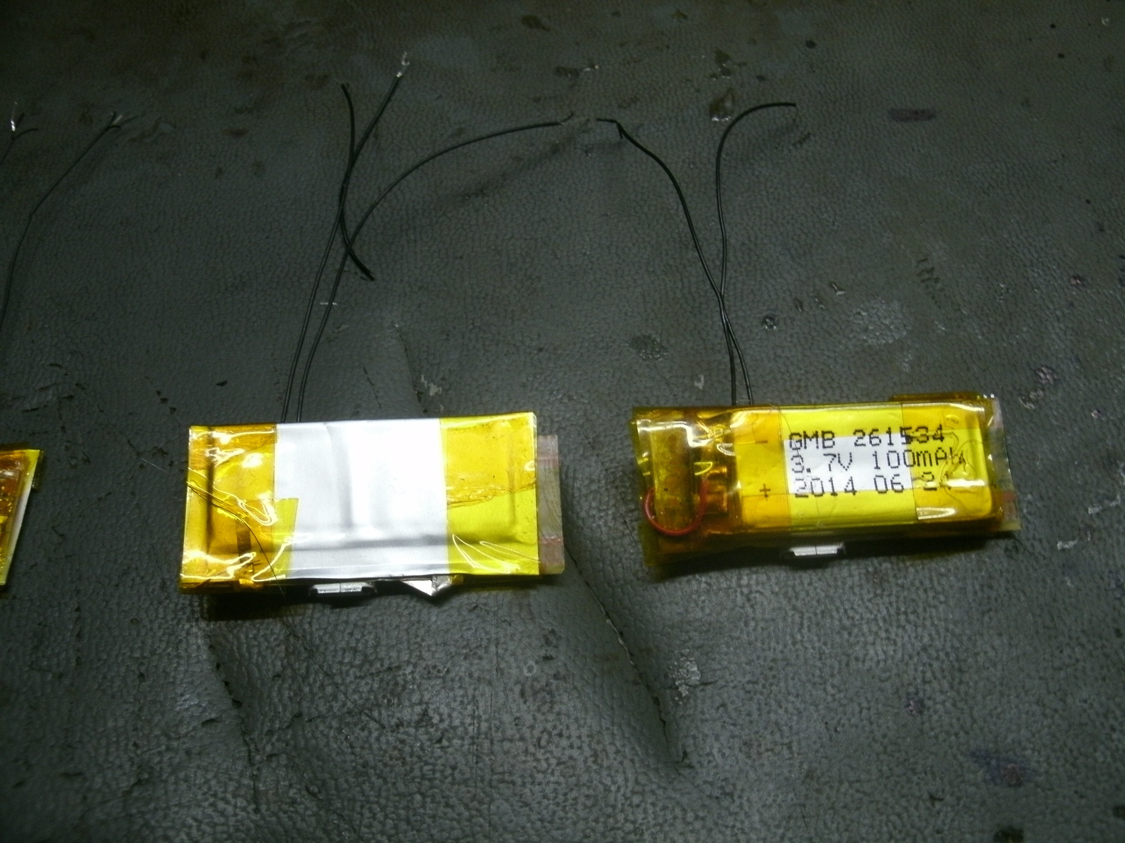
I was also only able to find one decent source for flexible LiPo batteries. The PGEB0054018 was selected for being narrow as well as thin.

If you add up all the quiescent current and average out the beacon current (about 20mAh for 3.5 ms every 10 seconds) draw you end up with about 7.4uA of average current draw. With that figure without solar charging using the 10mAh flexible battery you get a little over a month of beacons. The solar panel outputs 8.5 mA in ideal conditions. That's 1000 times the average current draw. Even running at 1/10 its optimal current it would only need to be lit up for about 15 minutes a day to stay charged.

This project is licensed under the UNLICENSE license. This means you are free to use it in anyway you can imagine. Reproduce it, sell it, modify it, do whatever you want with it.

  • 1 × BLE121LR-A-M256K Bluetooth LE Module
  • 1 × BQ25504RGTT Power Management ICs / Switching Regulators and ControllersSolar
  • 1 × LTC4071EMS8E#PBF Power Management ICs / Power Supply Support
  • 1 × SMT-0440-S-R Buzzer
  • 1 × PGEB0054018 Flexible LiPo Battery

View all 35 components

  • Jaspers Solar Banda has lost Power

    DrYerzinia06/27/2016 at 23:20 0 comments

    So last I checked in I said I was going to make a bandanna with a solar panel on it to get Jaspers solar panel out from his incredible fuzziness and into the light and it did improve run time. There was one other modification I made after some experimenting with the collar charging from dead. It has an issue in that it would oscillate because the start up current took such a big gulp the cutoff points of the BQ25504 solar charge chip protection circuit and the LTC4071 cut off points where fighting. One would come on, the device would try to start up taking a gulp of current and sinking the battery voltage and the other one would cut out so I changed the LTC4071s cut off voltage down to 2.7v and set up the BQ25504 to cut off at 3.7v.

    The collars charge lasted for a month which is an improvement over last time because of the higher cutoff voltage. The previous attempt would cut off at 3.2v while this one cut off at 3.7v or about 50% remaining battery which means we would have lasted twice as long if we had used the same amount of battery capacity!

    So we are almost there by my calculations we harvested about half the energy needed to run the system. And there is one obvious solution when we have all that realestate on the bandanna. More solar panel surface area.

    The slightly bigger than double SP3-37 solar panel should have just enough extra current to run the system indefinitely.

    There was another issue during this test. The bandanna light to rotate down so it covered his chest instead of staying on his bright back. I believe this is because of the weight of the electronics in the bandanna so for the next test I plan to only have the solar panel in the bandanna and run the wires down to the electronics which will be mounted at the bottom of the collar next to his tags.

    Fuzzy likes to fight the power which is why he always finds a way to keep the sun from shining on his solar panel.

    Since I brought in the battery protection circuit of the BQ25504 in the last design revision I decided to see if I thought the LTC4071 was still worth it. An extra 4 dollars for that chip is a bit much even if it does have an amazing 0.1nA cutout current the battery probably undoes that with internal leakage. So I went and measured the current being pulled with it bypassed and just using the BQ25505 as the cutout device. A measly 60nA, sure its 600x what the LTC4071 pulls but really its small enough to not matter. Even if the device was discharged to 10% of its battery capacity it would still take 2 years at a 60nA draw to drain it to 0%. So out with the LTC4071.

    I hope to be back in a few months to report that Jaspers collar hasn't lost a step with the new collar. Untill next time thanks for reading.

  • Solar Charging From Dead Battery now WORKS!

    DrYerzinia04/08/2016 at 14:44 0 comments

    So two logs ago I lamented about how my then current prototype would actually kill its battery further if it received light in an already dead state. This turned out to be an issue cause by the fact that the solar charge circuit always has the BLE module on its system load output, which also feeds the battery. With the battery cut off at 3.2 volts and charging through the body diode in the protection IC the system load was at approximately 3.8 volts but had no where near the current to boot up the module. This allowed current to leak through the module and turn on the transistor that powered up the buzzer that was tied directly to the battery.

    The new design fixed this by cutting of the power to the system load (BLE Module) with a MOSFET triggered by the VBATOK signal from the Solar Charge chip. This worked but presented an interesting new problem during testing. For testing in order to not have to wait as long as it takes to charge and discharge a battery I used a huge 0.1 Farad capacitor. This capacitor is still small enough that it will cause the battery (capacitor) voltage to drop significantly when the BLE module powers up. The problem stems from the fact that the battery protection IC charges through a MOSFET body diode when its shutoff. This means the voltage the battery sees in about 0.7 less than what the Solar Charge chip things its giving it. And the on voltage for the battery protection IC is 3.2v where the on voltage for the VBATOK signal is 3.9v. This had the effect of both signals coming up at very close together points. This coupled with the solar power cause the circuit to oscillate. The battery would connect followed by the system load coming on immediately which would drop out the capacitor voltage triggering the battery protection IC and repeat. This problem would have likely manifest itself with a real battery depending on how high the current load was initially so I'm glad I found it with the capacitor. The solution was to change the Low Battery Select voltage on the protection IC to 2.7 volts. Leaving enough room between the 2 voltages that it wouldn't oscillate.

    Now that the most important part of the circuit is working I'm getting ready for some more exciting tests. I have another board design with the Long Range Bluetooth module and I'm going to be putting them head to head to see which really gets the better range and if its the Long Range module is it worth the added cost.

    Also in Jasper's last real world test his collar only lasted a month before it stopped transmitting. This was probably because his collar was under his fur and didn't get any sun.

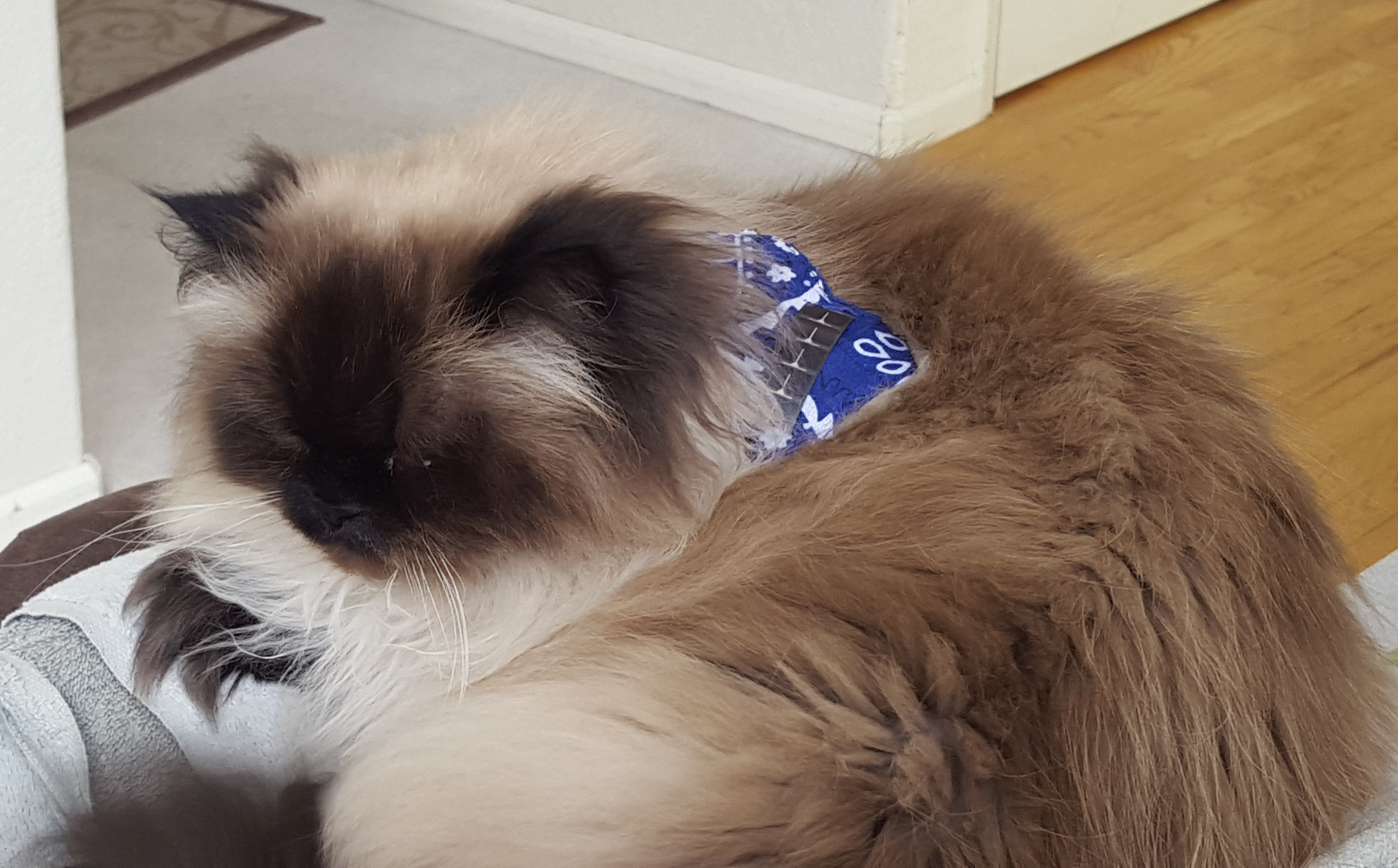
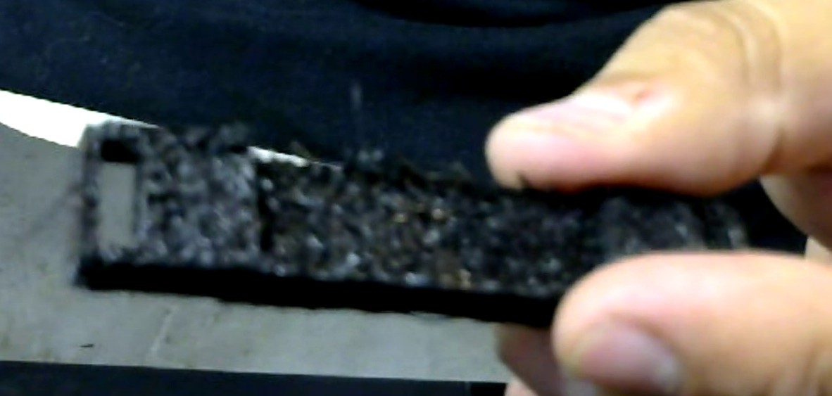
    So I got him a little bandanna to get the solar panel up over his back fur and into the sun. Hopefully it will also allow me to increase the panel size and get more energy from the ambient light.

    Thanks for reading. Check back soon for those new tests!

  • BLE Range Testing

    DrYerzinia09/14/2015 at 20:39 0 comments

    Did some range testing to see how far I could connect to the SolBLETracker r7 from with a couple different phones.

    The 360 degree video map video overlay didn't work quite like I wanted so here's that part unmolested. This is the part where I go over all the results of the testing.

    I tested with 3 phones; the Galaxy S6 Active, the LG D90, and the iPhone 4s. Managed to connect at the following distances:

    LG D90528 ft161 M
    Galaxy S6 Active612 ft187 M
    iPhone 4s761 ft232 M

    I managed about half of the 450 M distance quoted by the BLE121LR datasheet. But ofcourse towards the end I diden't have perfect line of sight and the BLE121LR doesn't have the recommended ground plane.

    A few things to note about these numbers. The iPhone 4s lost its connection after about 10 seconds at its furthest distance but it did work. When I walked back from where I couldn't hear beacons anymore to the max range test point the iPhone picked up the beacons slightly before the S6.

    It will be interesting to compare this to what I get with the BLE112 and see which has better range in this configuration.

    With the obstructions of housing the range of the radios is mostly confined within the house, but if the cats do get out and you need to track them down as long as they are somewhere along one of the streets you check while you have your phone out even if there quite a ways away you should still detect them and then once connected be able to pinpoint there location. The phones seem to have some directionality so rotating the phone and watching the RSSI can give you some indication of direction.

    So some things to come. I will be posting a simulation of searching for the cat hiding somewhere in the neighborhood soon hopefully so we can see how hard it is to find them with the tracker if they escape. I plan on having an Android app that you can load on an old phone that you can plug in somewhere near the center of the house and leave running. It will constantly scan for the cats and if they miss a beacon period notify you that it hasn't detected them. I've been doing this with a raspberry PI and a USB BLE scanner but thats been having some problems so now I'm going to try the same thing with android see if I can get it to work more consistently.

  • Revision 7 Problems

    DrYerzinia09/12/2015 at 00:05 0 comments

    The revision 7 prototype has a problem cold starting on solar power. Its worse than just that it doesn't cold start, when the system receives solar power in a dead battery state it will cause a further drain of the battery.

    The problem stems from the lack of isolation of the system load from the battery when the battery protection IC has it disconnected. This problem is a bit tricky to fix. Isolation can be done on the high side with a PFET driven by VBatOk. This is the solution recommended by the datasheet.

    VBatOk is an active high so the PFET must be driven by an inverted. The two key problems are we need an inverter that will draw next to no quiescent current and work referenced against VStor. VStor is set by a combination of factors. Its limited by both the battery voltage and the battery over-voltage set point. The lowest expected voltage is the battery cutout voltage of 3.2. However its also possible in long periods of disuse for the battery to drop lower. At lower voltages the inverter may be left with its output floating putting the isolation PFET in an undefined state. Testing of a prototype will determine if this solution will work.

    I am having 2 additional prototypes made for testing purposes. They will be used additionally to test the buzzer leakage current if there is any, for a performance comparison against the BLE112 radio module and finally to test the BQ25505 as an alternate energy harvesting chip.

    Switching to the BQ25505 may allow removal of the LTC4071 lowering BOM costs. The BQ25505 has a active low primary battery enable output so we would also not need the inverter. Its shipping mode with a 5nA quiescent current allows for it to replace the LTC4071 with sufficient performance.

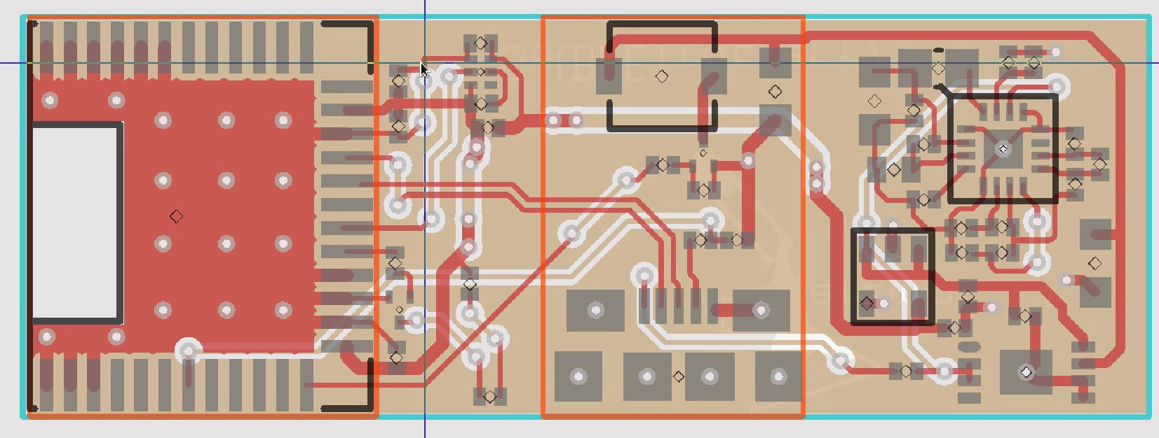
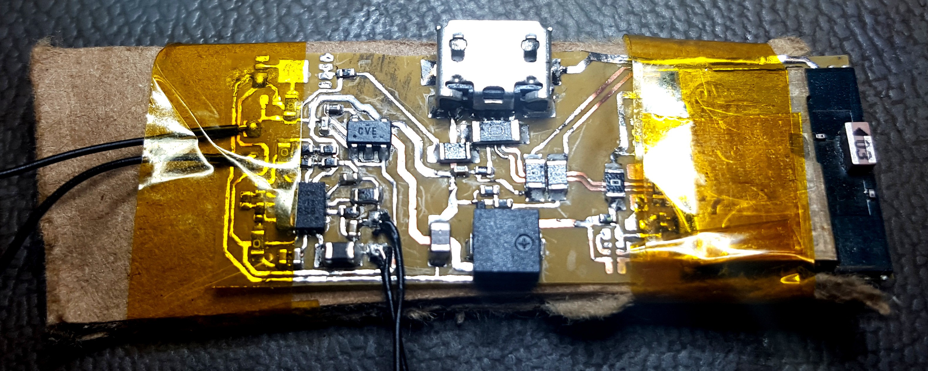
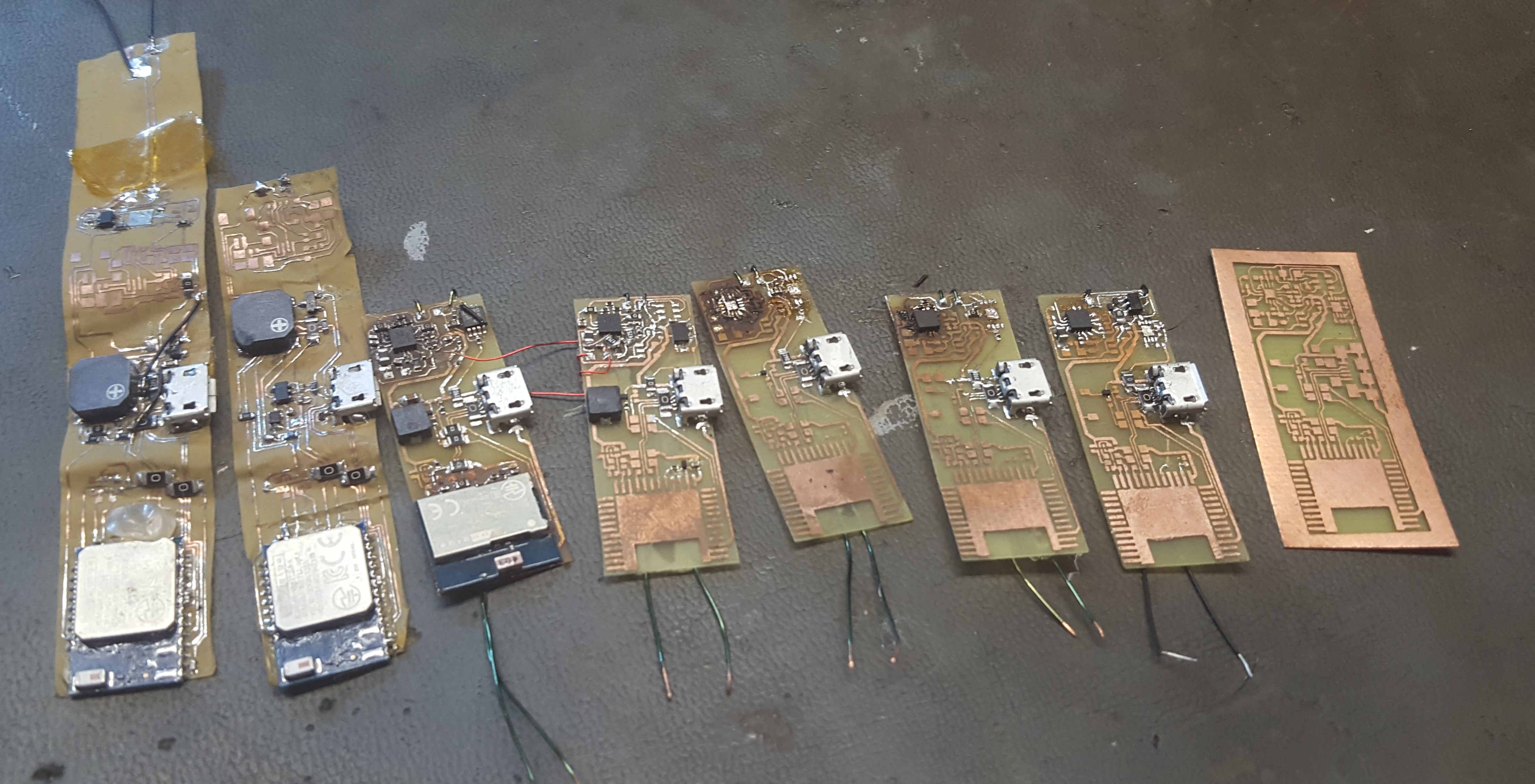
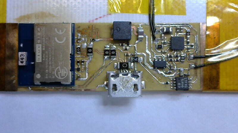
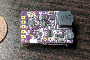
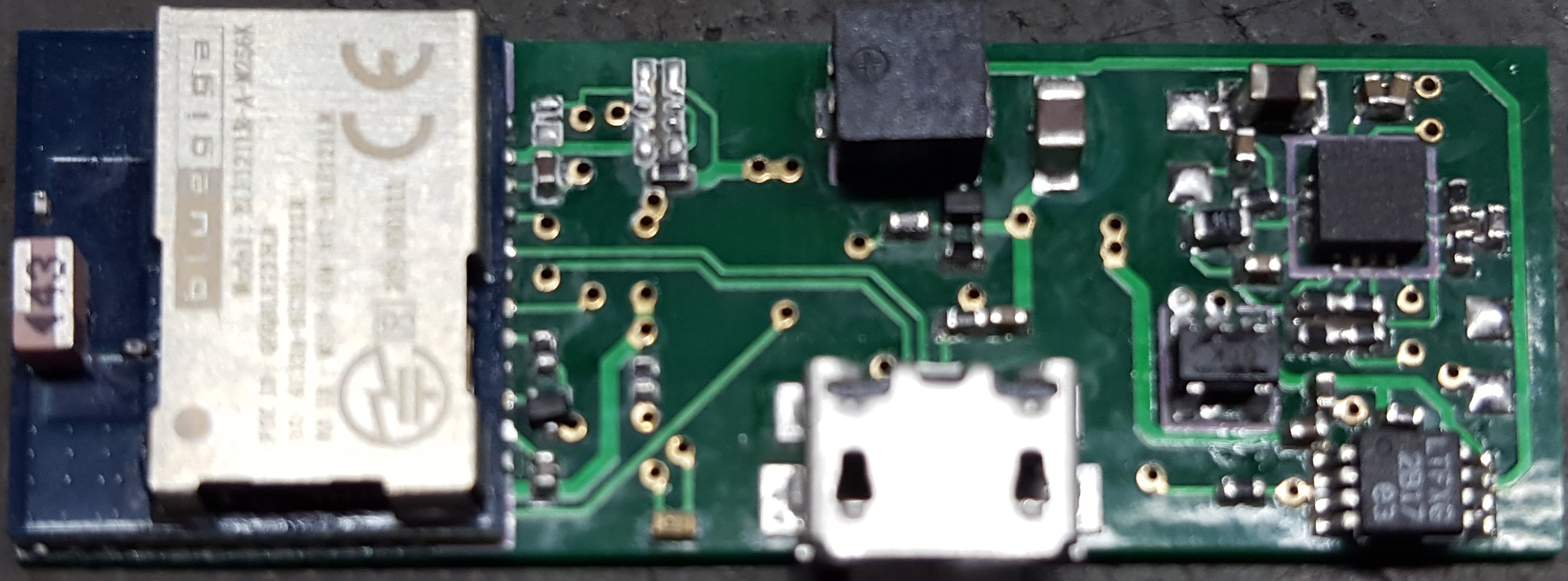
    The r7 prototype PCB's where obtained from PCBCart. Only 85$ for 50 boards and I got them all within a week and a half. The holes in the vias where a bit off center but they never broke the edge. The board quality was quite good. However the 0.4mm PCB's are not a flexible as I had hoped they would be. They don't bend much at all.PCB cart even threw in a nice stainless steel solder paste stencil. I used this to make the prototype board. The solder paste on the bottom of the BLE121LR ran together a bit but in spite of that every joint came out perfect on the first go. I was able to assemble, solder, and program the board in only 30 minutes. Much faster than my previous prototypes done with hand soldering.

  • Case and PCB Update

    DrYerzinia08/24/2015 at 23:03 0 comments

    The PCB is now at revision 7 and getting ready for a final professional prototyping build and the case design is still very much up in the air right now.

    I printed 6 different cases based on the threaded through collar design. The first 2 I printed with flexible filament. The first one printed ok, but after that I couldn't get the filament to feed right in my printer anymore and gave up on it. Instead I printed 4 more out of PLA to make sure all the dimensions where right and everything fit. Turns out I had some things wrong. The first thing was the side walls where too thin. Turns out my openSCAD equations weren't right and I was subtracting to much. The I realized I had my buzzer/microUSB holes on the wrong sides as well as it being a bit thicker than I wanted overall.

    My printers z-resolution is better than its x or y so I trimmed down the front back thickness to 0.7 mm. The wall sides need to be atleast thick enough to have 2 layers of PLA so they are set to 2 mm thick. I left 0.35 mm for the edge of the solar panels to slide into their pockets.

    The board sits in there pretty well but I realized with it thinner than the overall case the micro USB can't protrude one side while the buzzer is flush with the other. Since the r7 board is going to be 15 mm wide and the battery is 18 mm wide there is no way to reconcile that from case changes. Right now I'm planning to change batteries to solve the problem. A 2x12x12 mm battery that will sit over the power supply circuitry would allow it to be about 0.5 mm thinner and still retain most of its flexibility. Then I can match the width of the case to the width of the board and have the buzzer and micro USB both be flush.

    The way I'm printing now I can't fit the solar panels into the pockets in the case because the layers fuse together during printing. For this to work I will probably have to pause printing before this layer and insert the circuit board and solar panel. Then the printer can lay down the top layer over the flaps and seal it in.

    On the revision 7 design of the PCB I upgraded to using 2 layers. The difference in production costs is insignificant and it allowed me to narrow the board to 15 mm as well as add a nice ground plane and clean up some of the traces.

    All the power trance now have some width to them even though that's likely unnecessary and anywhere a part needs a ground it can just drop down to the bottom layer. The RF performance of the BLE121LR should also be improved by the larger ground plane.

    The last thing to look at is the testing of the collar. Right now I have one deployed in the field on Jasper. It spent a week in the basement on the pool table and is still running fine. Now its chilling out on Jaspers neck. Its been there for a day and still working. This version is using the thin curved PLA case construction. The circuit board is pretty much hanging out in the breeze but it seems to be holding up just fine.

    Everything just looks better with Kapton tape on it. That gold sheen makes it look like its meant to go out exploring in the vacuum of space!

  • Best Product Requirements

    DrYerzinia08/17/2015 at 10:42 0 comments

    All non hackaday people can ignore this post I just am putting this up so they can easily find all the requirements for the best product contest.

    Entry Round (Stage 1).Complete the following steps

    i.Personal Profile. Create a personal profile on hackaday.io, completing all required fields and following all instructions (required of each Participant, including each member of a team).

    • Obviously if this project exists this happened

    ii.Project Profile. Create a project profile on hackaday.io, completing all required fields and following all instructions (“Project Profile”). Tag the Project Profile with: HackadayPrize.

    • Obviously if this project exists this happened

    iii.On the Project Profile:

    a)Discuss the problem which has been chosen as the subject of the project

    • In the details section

    b)Discuss how this project will work to alleviate or solve the problem

    • In the details section

    c)Publish at least one (1) image to help illustrate how the project might be used. This may be a sketch, schematic, flow chart, rendering, or other type of image.

    • Third image in the gallery

    Quarterfinals (Stage 2). By 1:50 p.m. P.D.T. on August 17, 2015, complete the following steps:

    i.Complete all Stage One requirements

    • See above

    ii.Video. Create a video, no more than two (2) minutes in length, that shows the prototype in progress (i.e., what works, what does not work, what the Participant wants to improve). The video does not need to be “studio quality.” Upload the video to YouTube or Youku and tag the video with the keywords: HackadayPrize, quarterfinals.

    iii.Project Profile. On the Project Profile:

    a)Link to the video

    • See external links section on project page

    b)Update and add detail to info entered at the Entry Round stage

    • See project logs and details section (In details updated chip change and net change from r4 to r6)

    c)Show at least four (4) Project Log updates

    • Not including this log that's not really related I am up to 8

    d)Link to any repositories (e.g., Github)

    • See external links section, code, schematic, licensing, 3D models all in git repo.

    e)Post a system design document, including a preliminary components list. The system design document should show what is working and what the Participant is building toward

    • See external links, system design document was rather vague, should it be a picture of the system architecture, should it be everything. So I went all out and typed up a fairly detailed technical paper describing the system and testing done on it. More info to come soon to that I still want to describe the operation of the solar charge circuits and the quirks I experienced using it.
    • Currently posted system design document does not contain component list I'll get right on that but remember its all on the project page!
    • UPDATE: Design Document has parts list!

    f)Document all open-source licenses and permissions as well as any applicable third-party licenses/restrictions

    • The UNLICENSE, mentioned in details section as well as being in root of git REPO. Do what you want with it.

    Semifinals (Stage 3). By 1:50 p.m. P.D.T. on September 21, 2015, complete the following steps:

    i.Video. Create a video, no more than five (5) minutes in length, that shows a near complete prototype (i.e., what works, what does not work, what the Participant wants to improve). The video should describe the problem it is solving and demonstrate how it facilitates the solution. The video does not need to be “studio quality.” Upload the video to YouTube or Youku and tag the video with the keywords: HackadayPrize, semifinals.

    • Yes I know its the same prototype as the quarter finals but they are due the same day for best product so what do you expect!
    • I would have done a video on the r4 or r5 for quarter finals but I was to busy getting it working so I could mail some prototypes. Haven't spent a free moment doing anything but this project in 3 weeks!

    ii.Project Profile. On the Project Profile:

    a)Link to the new video

    • See external links section and this post

    b)Update and add...

    Read more »

  • First shot at a case

    DrYerzinia08/17/2015 at 08:53 0 comments

    This was my first attempt at printing the case design. This model is designed to have the collar threaded through it. Its low profile about 4mm thick. The solar cell sets in the cavity's at the top and the board sits in the well below with holes for the buzzer and the micro USB. I haven't figured out what to do with the LED yet it will clearly need some form of light pipe.

    The model looks nice but unfortunately my 3D printer is just not up to snuff to print it.

    You can see one of the walls is destroyed and its all kinds of messy. I currently have a very limited 3D printer. It has no heated bed, a remote extruder, no extruder fan and there is a space between the knurling bolt and the tube that allows the filament to pinch so I have to be vigilant and push it in with a screwdriver so it keeps feeding to print flexible filament.

    I could add a heated bed but I don't think a direct feed extruder is possible with this design, some one correct me if I'm wrong. Right now I'm looking to get a TAZ 4, hopefully I'll have some money for that in the next couple of months.

    The case should work If I get it to print right. I'll try again soon.

  • Advertisement Burst Testing

    DrYerzinia08/16/2015 at 07:32 0 comments

    I made myself a 4th copy of the revision 6 prototype after sending off the first 3 to hackaday.

    Its missing the LTC4071 and battery because I've run out. I had to scavenge some of the parts from older prototypes. Now that I got paid again this week I can order more parts to finish it.

    The first test I did was a comparison of current consumption between single channel advertising and all three channel advertising. I tested with the 1 second interval which I had previously recorded an average current consumption of 17.35368 uA.

    33.56 uA which is about double the single channel advertisement. I has expected triple but I guess the time spent switching between active and power mode 2 is a significant amount of the power used transmitting so when you average that in with the actual time spend advertising it end up only needing 2x as much current. Knowing this I can calculate how well my idea of using a 640mS interval for a 10 second burst every 2 minutes will work out.


    That's pretty close to being my goal of 10uA so I programmed it in and tested it. I ended up measuring 15 uA.

    Now that I had it working with appropriate current consumption I needed to see how hard it was to connect to. The first thing I discovered was that the autoConnect feature of androids BLE API is nowhere near aggressive enough to catch it in the 10 seconds. It occasionally got it but I would have to wat 5-10 minutes! But I guess its designed to run in the background all the time so it has to be rather power conservative. When I write my Android app I'll be sure to write a foreground service that attempts to connect more aggressively. When I watched the scanner and hit connect when I first saw it I managed to get a connection every try even when I was outside on the far corner of the house with a signal strenth of 96 dBm.

    These results are quite good. A purpose built device in the house would be able to monitor BLE and alert you by text message if it missed 2 burst periods and should be quite reliable. And scanning with the phone anywhere in the house should always find that cat within 2 minutes. This coupled with the fact that we can run on only 15 uA means we have a workable solar powered BLE tracker! I'm going to print the first prototype case tonight so expect info on that tommorow.

  • Shipped 3 Best Product Prototypes

    DrYerzinia08/15/2015 at 04:05 0 comments

    Managed to finish all 3 prototypes just in time. Testing completed at 7:30AM after working 16 consecutive hours to get the last 2 done. 30 minutes before the post office opens. I have pretty much worked nonstop, every moment of my free time this last week to get these prototypes ready to ship. And I just barley made it.

    Tested working before shipping. You can see the 3 devices detected on the scanner app on the phone in the background. If you are the person at hackaday trying to test my prototypes and you can't scan them an important note. They are shipped with the battery protection IC in shipping mode. You have to briefly apply power to them on the micro USB port to activate them. When you do be careful because the PCB is super thin polyimide film so its best to firmly grip the device by the micro USB connector when plugging and unplugging or you may tear the polyimide film and trace on it.

    Odd one out. Only had 2 working flexible LiPO batteries left so the last prototype had to use a bigger different battery. What it lost in thickness it more than makes up for in battery life.

    Solar panels strapped on. Not exactly the most stable configuration but it will do. It pretty much does everything but stay attached to a cats collar. Look out for a post this weekend showing the 3D printed case prototype.

    On the way to the post office, got the address and the trackers. Sending it overnight.

    The fallen comrades of revision 6. Some obsolete still work, some had the FR4 epoxy erupt under IR rework, some didn't etch right. All in all I've made a lot of freaking boards and soldered a lot of tiny tiny parts. You can see I was rather stingy with the radios as they are the most expensive part. Putting it on last and only if everything else was functional.

    Now I just have to make another one for testing over the weekend...

  • Sol BLE Tracker r6 Current Consumption Tests

    DrYerzinia08/15/2015 at 03:18 0 comments

    Before I get into the tests an update about the last week. I have a lot of footage and pictures from testing to go through still and make some videos and more logs because I was crunched for time to make the 3 prototypes to send in for the best product competition and didn't have time to edit the videos and write up the projects logs so expect a lot of stuff this weekend.

    This set of tests analyzes the current consumption of the device with various beacon rates advertising only on channel 39. The test was conducted by running the device from a capacitor and calculating how much energy was drained from the capacitor by measuring the voltage change. This information was then converted to a average current consumption figure.

    Above you can see a picture of the setup. I use the stopwatch on my phone to measure the time elapsed, a Fluke 87V to measure voltage, and a 1000uF cap as the power storage. The test is started by unplugging the USB power to the circuit. We can use all this information to calculate current consumption by the following formulas:

    First we calculate power consumption by taking the difference of the energy in the capacitors divided by elapsed time.

    Next we estimate the power drained by the meter at the low voltage point so our estimate is conservative.

    We subtract the estimated meter power consumption to get the power consumed by the device under tests.

    Finally we divide power by the midpoint voltage of the test to calculate average current consumption

    Plugging in for everything we end up with for the 10.24 second interval case:

    So for a advertising interval of 10.24 seconds we get an average current consumption of ~3uA.

    Above are the plots for the current consumption. By inverting the advertising interval to get advertisements per second we get a graph that has a linear relationship. Running a linear regression on that we get:

    So now we can estimate current consumption from the advertisement interval. The correlation coeffecent for this line is 0.999489068 so it is a very good fit.

    In addition to testing current consumption I also did a bit of testing how hard it was to connect to the devices at each advertisement interval. Unfortunately it turns out to be nearly impossible to connect to a device at distance with an interval over 1 second. To maintain the low 10uA current consumption and improve range I am going to modify the firmware to beacon with a 320mS interval every 120 seconds for 10 seconds. This means to connect to the device you will have to wait up to 110 seconds for the packet burst. But once connected communication is continuous so its easier to find the device from that point on.

    Another thing I will have to test is to see how multi-channel advertising works. It might send a packet on each of the 3 advertising channels each interval in which case that would triple the current consumption. If this is the case I will have to either decrease the interval to 1 second or only do the burst every 6 minutes to maintain the 10uA. The problem with the single channel advertisements is that when and Android device scans for BLE devices it seems to linger on each channel for several seconds rather than rapidly jumping which means it could miss the entire burst on a single channel. You can see this behavior in the image below.

    The blue line is the signal from the r6 prototype. The red from r2. r2 is using a 320mS interval on all advertising channels while r6 is using a 320mS interval on only advertising channel 39. you can see the large 7 second gaps in reception where it stops scanning channel 39.

    And finally a close up of the first revision 6 prototype fresh off the soldering iron.

View all 14 project logs

Enjoy this project?

Share

Discussions

Simon Merrett wrote 11/18/2019 at 18:05 point

Thanks for introducing me to the Flex Solar Cells products!

  Are you sure? yes | no

Sebastian Holmqvist wrote 03/05/2016 at 15:46 point

Nice project!

Particularly interested in the SP3-12 solution. Looks like a 3.7V LiPo you're using. Is that with a boost circuit of some sort? Couldn't decipher from the screenshots.

  Are you sure? yes | no

DrYerzinia wrote 03/18/2016 at 01:55 point

The BQ25504 is a energy harvesting chip with a boost converter.  Also the LTC4701 is for charging via USB as well as low voltage protection.

  Are you sure? yes | no

egonspengleruk wrote 09/14/2015 at 16:26 point

What format are the Schematic and PCB files? Is it http://pcb.geda-project.org/?

  Are you sure? yes | no

DrYerzinia wrote 09/14/2015 at 16:31 point

Yes the Schematics and PCB files are from the gEDA suite.  I'll link a zip with the latest Gerber today too.

  Are you sure? yes | no

MicroPrototype & Design wrote 09/02/2015 at 13:13 point

Where did you locate the battery ?  ( PGEB0054018 )

  Are you sure? yes | no

DrYerzinia wrote 09/02/2015 at 14:30 point

The battery is from PowerStream: http://www.powerstream.com/thin-lithium-ion.htm

Its also the second most expensive component on the BOM!  Well in small quantity any way.  Less than 10 units and you are paying 10 bucks a pop.  1000+ and you finally get down to 3.95$ each.

They will make custom battery designs if you order 2000+ units so if you need a really fancy custom battery for an interesting application it probably wont make it into your prototype but you could get it in a production run.  That's one thing I'm considering long term.  But like I said in one of my videos I'm not sure I trust them to hold up long term flexibility wise.  I'll have to do some testing of there tolerance to multiple flexions and post it here sometime.

  Are you sure? yes | no

david wrote 09/02/2015 at 11:10 point

Hey, really nice work! You can user youre small solar supply to power ather projects. For example in a smartstrap for the pebble time smartwatch. You have developt it ready, why dont power a watch with that? 

  Are you sure? yes | no

DrYerzinia wrote 09/02/2015 at 14:25 point

It's certainly possible.  However the pebble smart watch draws quite a bit of juice in comparison to what I'm doing.  It has a 130 mAh battery that lasts for 7 days so:

0.13 AH / 168 Hours = 773 uA

That's 77 x the current draw my implementation uses so there is no way it can be powered by ambient light.  It would have to get direct sun.  It would use 130 / 7 = 18 mAh a day so we would have to be in direct sun long enough to charge it.  Since the measured direct sun charge current was 3 mA thats 18 mAh / 3 mA = 5 hours.  5 hours is a long time for anyone to be in the sun but I guess if your going to spend all your time outside it the hot sun it would work.

Alternatively you could use a solar panel 5x bigger and then you just need one hour of sun and you could get that on a morning run or the like.

Another possibility is using a Thermometric generator that pulls from your body heat.  I haven't had the opportunity to study the kinds of power you could extract from such a wrist mounted device, particularly with a reasonably uncumbersome heat sink on your wrist so I cant say how well it would work but its an idea.

  Are you sure? yes | no

Arya wrote 09/02/2015 at 10:24 point

Hi! I'd be interested in buying some or maybe rolling some of my own. Could be a nice thing to have - not only for pets, but for posessions as well - which is actually my main concern =) I love wearables, and this seems like a nice addition to a Linux-driven wearable meant to track every aspect of your life, as an example. How much would be the parts cost (with PCBs) and the price of a ready unit? 

  Are you sure? yes | no

DrYerzinia wrote 09/02/2015 at 14:17 point

Depends on how many you make.  Right now the small quantity cost is about 50$ a unit mostly due to the BLE radio being 7$ more than its 1000+ cost and the battery 9$ more than in its 1000+ cost.  The other major expense is the flex PCB.  If you go with a 0.5 mm PCB you can get it pretty cheaply priced for about 10 units, maybe 10$ a board but for good quality flex your looking at a few hundred dollars setup cost.  I'm looking at doing a 10 prototype run and its ending up being about 100$ a board.

In large quantity's it comes down to be under about 30$ a piece though.

  Are you sure? yes | no

Michael Adams wrote 08/17/2015 at 17:58 point

Okay thanks i would love the prototype...!!

  Are you sure? yes | no

mikemwambia wrote 08/01/2015 at 01:37 point

I am very interested in your project....!!

  Are you sure? yes | no

DrYerzinia wrote 08/17/2015 at 10:48 point

Thank you.  I'll be ordering some prototype PCB's from FlexPCB this month, 850$ for the prototypes...

For being the first person to comment I'd be happy to send you one if you'd like once I have a final prototype around the end of next month just let me know.

As you can see from the project logs this tracker is really only house range but I have 2 other versions planned.  This is a low cost short range unit.  I'm also planning to do a cellular GPS version (Heavier, Bigger, probably needs charging) and a version based on the SX1272 chip which will need a base station.  My experimenting with those chips is a range of 1-2 miles in the city.  Hills really kill the signal unfortunately.

I'll comment links to those project pages here when there up.

  Are you sure? yes | no

Similar Projects

Does this project spark your interest?

Become a member to follow this project and never miss any updates