 ben biles
I the Got 4 x PGA2500's working and controlled with the arduino. I'm not going to pretend it was smooth sailing. lots of nasty noises hums and crackles !!! but it is at leaast working well enough to test things. I used double sided 2.54 proto board for the first time and I can't say did very well using it. I found solder was leaking through the holes and making bad connections under the proto adapters making it impossible to find the bad connections. I'm sure there is a proper way to use the double sided board but I think I prefer single sided.
The PGA2500's work in a chain and are controlled as a serial shift register. I used the arduino wire library. This confused me to begin with since the fist 16bits you write are for the last PGA2500 in the chain !
things are a bit back to front but simple when you understand the shift register concept.
My protoype board is not that great but I mainly want to experiment with adding phantom power and changing capacitors and resistors around for the audio IO connection to the ADC and test the Phantom power switching on each channel.
The +-5v dual rail power supply could be cleaner, I need to add some RC and experiment with that too before I print up the pre amp PCB board prototype.
One if the PGA2500's got very hot very quickly at one point , it did'nt burn but I'm still not sure of what caused it. My Murrata dual rail power supply could be at fault, it had a slightly high - output at 5.6v at one point . I'm not sure what caused this.
The main thing I've learned on this board is that I should really have built a single channel Pre amp first with the PGA2500 to get a better understanding of its anommalys.. ( sorry have no idea how to spell ) hackaday ? can we get a spell check on the site ?
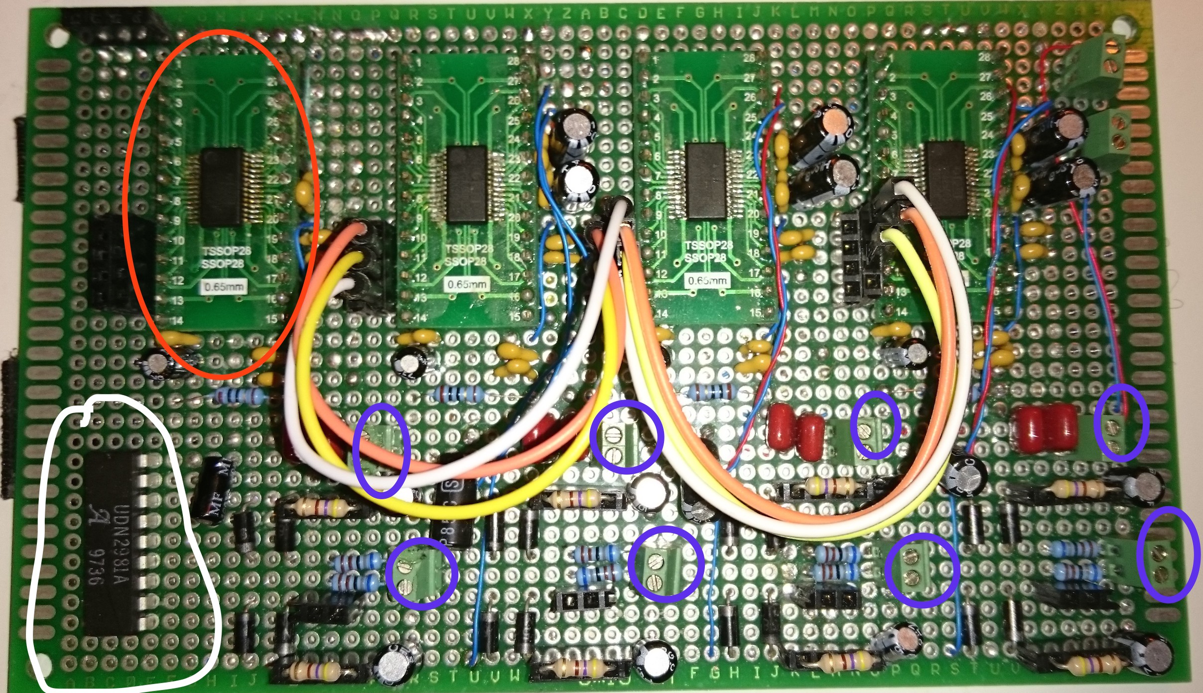
red ring [ PGA2500 that got very hot !! I unwired it ]
white ring [ phantom power supply on/off to each channel. Will be hooked up to GPIO pins
Blue rings [ balanced audio IO 4 channels ]
I can't say I'm really happy with this test board. It constantly gives me the feeling its about
to go out of control and burn my ADC or something ! the gain control is very smooth and you can adjust gain on all channels at the same time etc without poping. Its zero crossing etc.
perhaps things will work better on the PCB prototype since I can get the capacitors closer to the IC's and the ugly wire jumpers for the serial contol from the MC are perhaps too long.
I do have diode protection for the inputs so hopfuly I wont blow up too much testing the phantom power.
Discussions
Become a Hackaday.io Member
Create an account to leave a comment. Already have an account? Log In.