 ben biles
OK its all working fine so I just need to upgrade the micro to get another SAI channel add XMOS and gigabyte ethernet.. what could possibly go wrong ??
re-writing the firmware with new pins and DMA channels etc is done and its starting to come to life.
Bluetooth works and so does the 1" screen on i2c2 for debugging. The DMA channels initialize and the player pushes audio samples through the DMA channel etc.
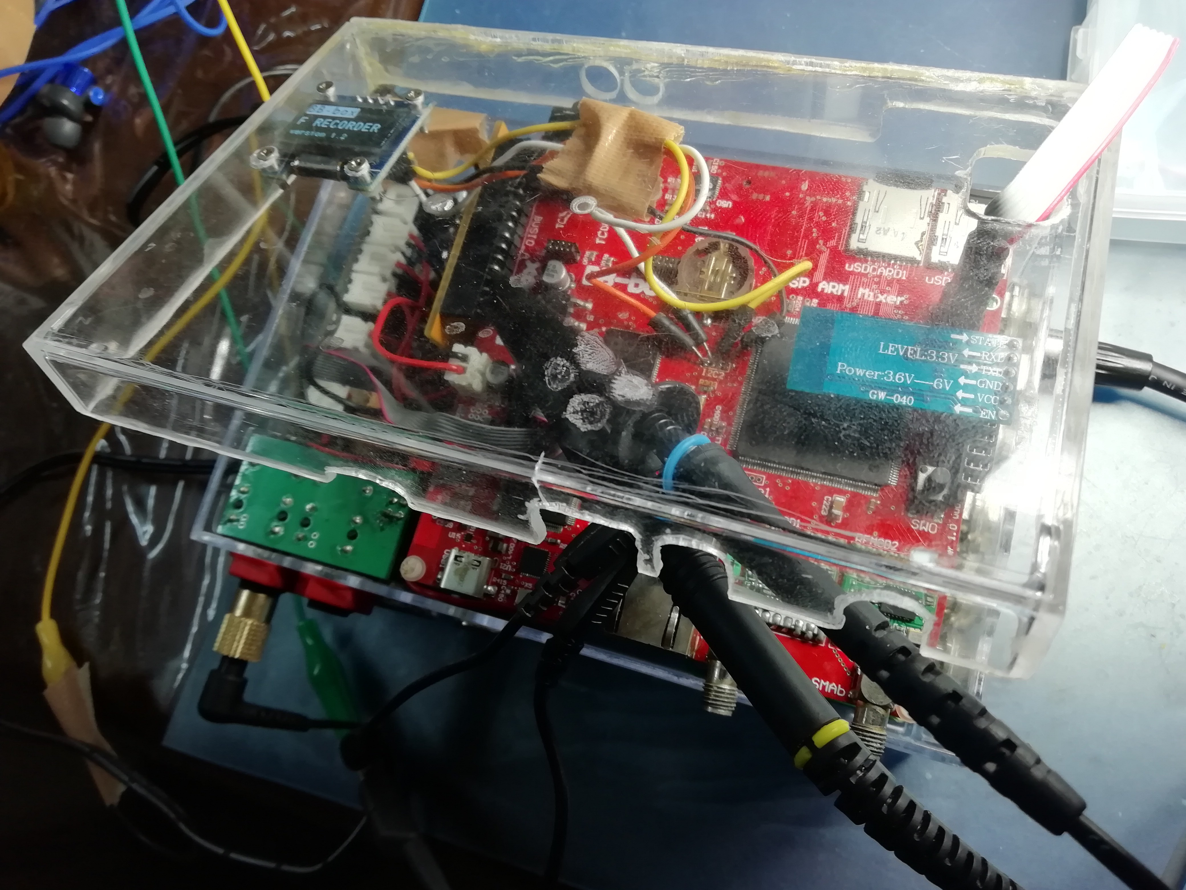
Then I probe the FS / TDM line on the DAC and I can see audio on all 8 channels of the TDM line. FS is not changing according to the WAV file the player code is playing.
The player finds the sample rate in the WAV header and should change the SAI port clock according to the sample rate of the file. The TDM channel number should also change ( usually to 2 for normal stereo ) The Channels switch on in RECORD mode individually but no audio getting through to DAC yet. I still need to check SPI port to analogue preamps is actually working although the current draw goes up when i switch on preamp 1 so looks like it is!
I'm running the STM32H7 with external HSE TCXO at 25mhz as I did STM32 F7
The player should change the SAI peripheral clock like this and it worked on stm32f7..
__weak HAL_StatusTypeDef BSP_AUDIO_OUT_ClockConfig(SAI_HandleTypeDef *hsai, uint32_t AudioFreq, void *Params)
{

  RCC_PeriphCLKInitTypeDef rcc_ex_clk_init_struct;

 // HAL_RCCEx_GetPeriphCLKConfig(&rcc_ex_clk_init_struct);  // BEN do i need to run this ?

HAL_StatusTypeDef ret = HAL_OK;

  /* Set the PLL configuration according to the audio frequency */
   if((AudioFreq == AUDIO_FREQUENCY_11K) || (AudioFreq == AUDIO_FREQUENCY_22K) || (AudioFreq == AUDIO_FREQUENCY_44K))
  {

    /* SAI clock config */
    /* Configure PLLSAI prescalers */
    /* PLL2_VCO Input = HSE_VALUE/PLL2M = 1 Mhz */
    /* PLL2_VCO Output = PLL2_VCO Input * PLL2N = 429 Mhz */
    /* SAI_CLK_x = PLL2_VCO Output/PLL2P = 429/38 = 11.267 Mhz */

rcc_ex_clk_init_struct.PeriphClockSelection = RCC_PERIPHCLK_SAI23;
    rcc_ex_clk_init_struct.Sai23ClockSelection = RCC_SAI23CLKSOURCE_PLL2;  // SAI23 clock selection !!! SAI2 shares peroph clock with SAI3?

rcc_ex_clk_init_struct.PLL2.PLL2P = 38;  // PLL2P: Division factor for system clock. Min_Data = 2 and Max_Data = 128
rcc_ex_clk_init_struct.PLL2.PLL2Q = 1;
rcc_ex_clk_init_struct.PLL2.PLL2R = 1;
rcc_ex_clk_init_struct.PLL2.PLL2N = 429;  // PLL2N: Multiplication factor for PLL2 VCO output clock. Min_Data = 4 and Max_Data = 512
rcc_ex_clk_init_struct.PLL2.PLL2FRACN = 0;
rcc_ex_clk_init_struct.PLL2.PLL2M = 25;


if (HAL_RCCEx_PeriphCLKConfig(&rcc_ex_clk_init_struct) != HAL_OK)
{
ret = HAL_ERROR;
}


  }
  else /* AUDIO_FREQUENCY_8K, AUDIO_FREQUENCY_16K, AUDIO_FREQUENCY_48K, AUDIO_FREQUENCY_96K, AUDIO_FREQUENCY_192K */
  {

    /* SAI clock config */
    /* Configure PLLSAI prescalers */
    /* PLL2_VCO Input = HSE_VALUE/PLL2M = 1 Mhz */
    /* PLL2_VCO Output = PLL2_VCO Input * PLL2N = 344 Mhz */
    /* SAI_CLK_x = PLL2_VCO Output/PLL2P = 344/7 = 49.333 Mhz */

    rcc_ex_clk_init_struct.PeriphClockSelection = RCC_PERIPHCLK_SAI2;
    rcc_ex_clk_init_struct.Sai23ClockSelection = RCC_SAI2CLKSOURCE_PLL2;  // // SAI23 clock selection !!!

 rcc_ex_clk_init_struct.PLL2.PLL2P = 7; //   PLL2P: Division factor for system clock. Min_Data = 2 and Max_Data = 128
 rcc_ex_clk_init_struct.PLL2.PLL2Q = 1; //   PLL2Q: Division factor for peripheral clocks. Min_Data = 1 and Max_Data = 128
 rcc_ex_clk_init_struct.PLL2.PLL2R = 1; //   PLL2R: Division factor for peripheral clocks. Min_Data = 1 and Max_Data = 128
 rcc_ex_clk_init_struct.PLL2.PLL2N = 344; // PLL2N: Multiplication factor for PLL2 VCO output clock. Min_Data = 4 and Max_Data = 512
 rcc_ex_clk_init_struct.PLL2.PLL2FRACN = 0;//PLL2FRACN: Specifies Fractional Part Of The Multiplication Factor for PLL2 VCO It should be a value between 0 and 8191
 rcc_ex_clk_init_struct.PLL2.PLL2M = 25;  // PLL2M: Division factor for PLL2 VCO input clock. Min_Data = 1 and Max_Data = 63

if (HAL_RCCEx_PeriphCLKConfig(&rcc_ex_clk_init_struct) != HAL_OK)
{
ret = HAL_ERROR;
}

}

  return ret; // should return HAL_OK
}
The clock RCC_PERIPHCLK_SAI2 = RCC_PERIPHCLK_SAI23
shared peripheral clock between SAI 2 and 3 ! !!!
I'm slowly getting there, but I'm wishing I included some easy hook onto probe pins now between on TDM lines between MICRO and ADAU1467 and perhaps TDM between XMOS and DSP ! of course that's easier said than done on a 4 layer board with so many signal lines.
The next job is to step through the code and check the TDM active slot number is being adjusted as it was in STM32F7.
Discussions
Become a Hackaday.io Member
Create an account to leave a comment. Already have an account? Log In.