We have all seen RGB LED mixers. By varying the duty cycle of each of the LED elements, you can create a variety of colors. If you use reasonably fast and smooth transitions, we perceive a very pleasing effect.
In this project, I am creating a single chip RGB color mixer for about $2. The PIC 12F1572 is ideally suited for the function as it has three pulse width modulators (PWM) – all on an 8-pin chip for about $1.
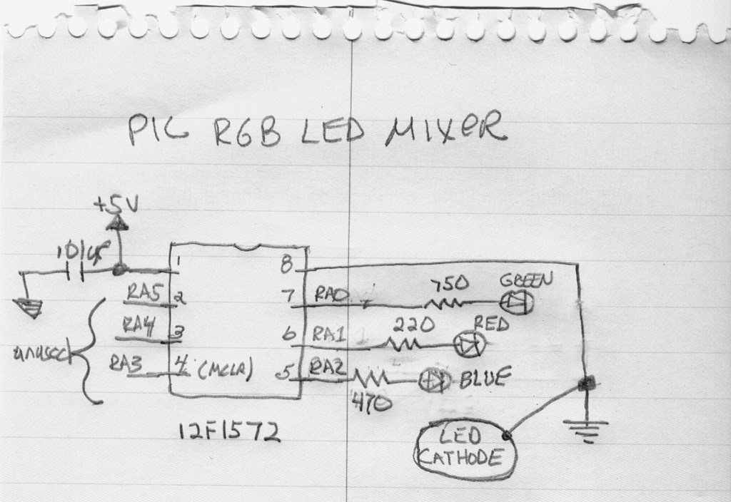
The circuit contains only a few components – the 1572, and RGB LED (common cathode), three resistors (carefully chosen) and a single bypass capacitor. It can’t get much simpler.
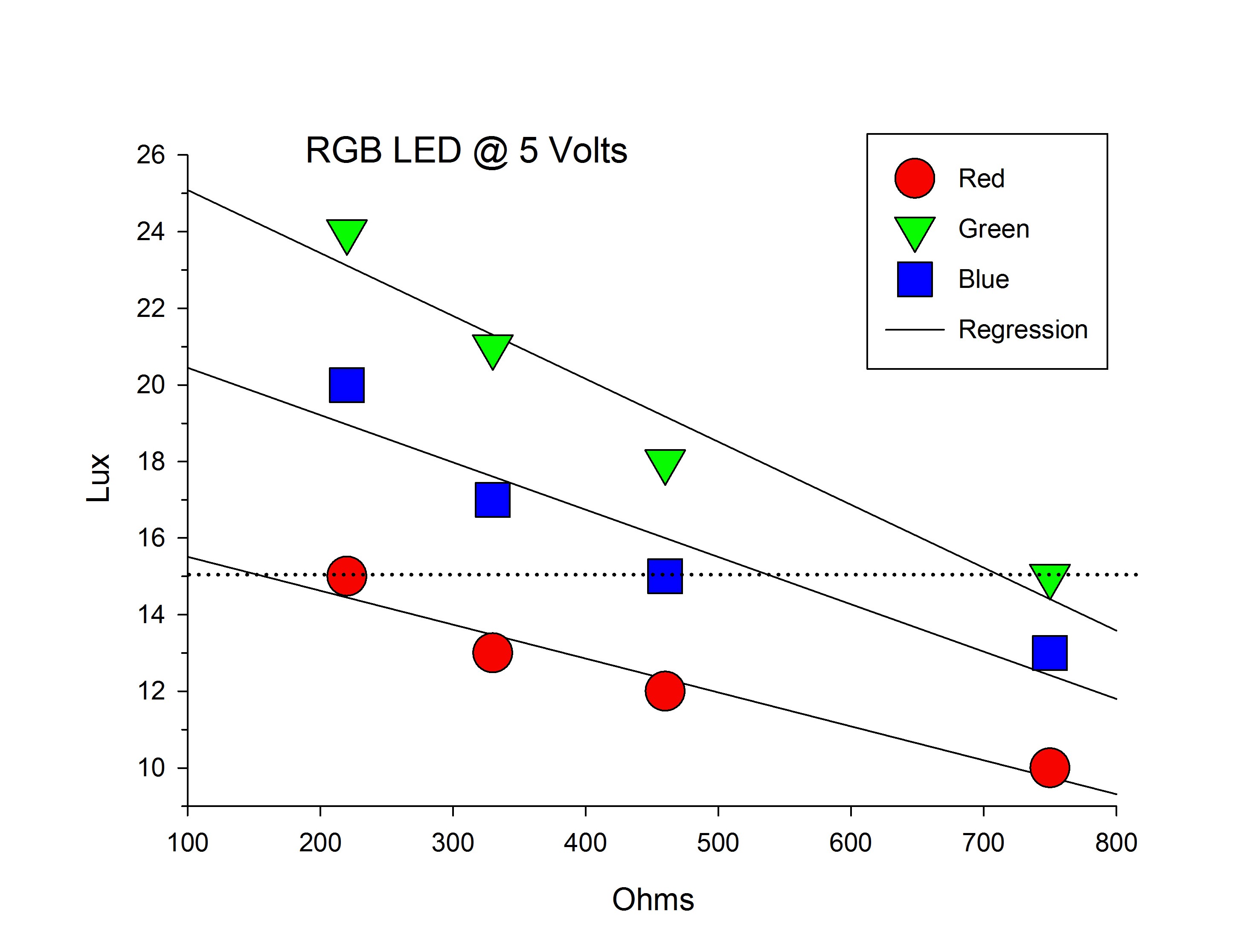
I chose the resistor values based on measuring the output of each RGB channel using a BH1750 light sensor interfaced to an Arduino UNO.I used a range of resistor values that I had that also kept the current (at 5V) below the maximum specification for the LED. The graph shows the output for the elements (in Lux) for each of the elements at each resistance value. From there, I looked for the closest fit using the resistors I had that would produce an equal lux value for each element. Not ideal, but within my resources, it is a reasonable approach.
I think that the RGB LED that I used was a Kingbright WP154ASUREQBFZGW – I can’t be absolutely certain because it was in my parts box, but that is my recollection. There is nothing particularly special about the LED and as I recall, it was less than $1.
Finally, I used a ping-pong ball for a light diffuser. I drilled a small hole and placed it right over the LED. I saw this little trick somewhere and it works quite well.
The code is not trivial and represented the real challenge. I had to figure out how to use the PWMs and Microchip has AN1562 which is a good starting point. The PWMs are 16 bit – that’s 65536 levels. I quickly determined that was more than I needed. I ended it up using 41 values (including 0) in a table. The values were chosen to represent a logarithmic scale because that is what I remember from my understanding of psychophysics, perception and sensation. In truth, the table is not in equal log units and varies between .025-.200. These were determined empirically aiming toward the greatest definition at place along the duty-cycle continuum where I could perceive a difference.
You can judge for yourself how well this works by looking at the video, which emulates an ROYGBIV cycle. In reality, the transitions are even smoother than the video – likely owing to being shot using my old Powershot point and click camera.
Cheers.
DrG


 Grayson Schlichting
 gianlucag
 MagicWolfi
 Thomas Chanon Wangtrirat
Can I see the code please
..I am also doing some project similar to this
on the same controller..:)