 David McEwan
Overview
There are a few distinct parts to the mcdox project:
- Case
- Hand PCB
- Controller
- Keycaps
- Firmware
Each of these parts is a good project on their own and, for me, none of these are really finished yet.
The case is made from layers of 5mm and 3mm acrylic, laser cut and held together with M3 bolts, similar to the Lister cases for the ErgoDox but with crucial differences.
The hand PCB just connects all the switches in the same matrix as the ErgoDox and packs the connections conveniently for the controller to work with.
The controller takes the switch matrix and implements the layout and USB connection to the host computer.
The keycaps are the actual pieces of plastic you touch when typing and are still the most expensive part of a custom keyboard.
The firmware runs on a small microprocessor. Currently, I'm using a port of the TMK keyboard firmware.
Why I started this project
I work with a computer keyboard about 8 hours a day and after about 2 years I noticed my finger joints were starting to get painful.
I also wanted to learn to touchtype but the pain made the dexterity required quite difficult. I wondered if there might some way to ease the pain and bring back the dexterity so started looking at alternatives.
First, I tried using the Dvorak layout. https://en.wikipedia.org/wiki/Dvorak_Simplified_Keyboard
That helped with the dexterity and touchtyping and got to the point where I could confirm that it was a superior layout for me and I could type faster with less mis-types than the UK qwerty layout I'd been used to.
Unfortunately, this increase in speed meant that I was using my finger more, so the pain got a bit worse.
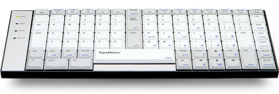
Figuring that by using a different layout I was already a bit of a keyboard geek, I decided to embrace that and read up about different ergonomic styles. The articles on the Truly Ergonomic Computer Keyboard and the Type Matrix convinced me to try a matrix layout instead of the usual staggered layout.
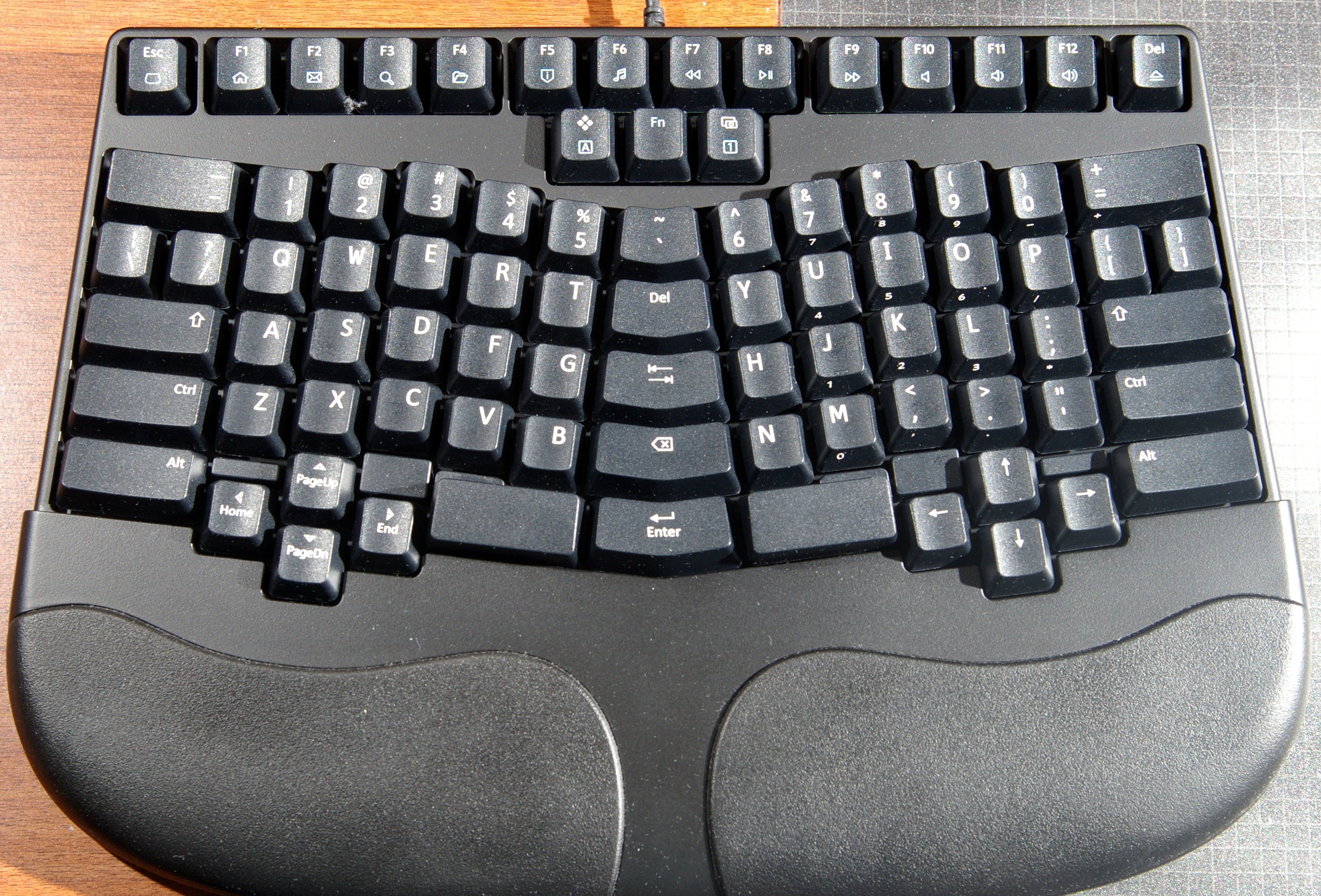
https://www.trulyergonomic.com/store/benefits
 http://www.typematrix.com/2030/features.php
If you look at a normal qwerty you'll notice that Q, A, and Z are not directly under each other but stagger off to the right. A matrix layout simply puts Q, A, and Z in a vertical line, and the same for other columns. I wasn't quite ready to splash out 200 quid on a TECK and I liked the idea of the "skin" cover on the TM2030 so that's what I went for.
I was very happy with this for about 6 months but there were a few things that I knew weren't quite right like having to turn on the Dvorak mode twice every time I used my Windows computer at work because Windows drops the power to USB devices during bootup/resume (None of my Linux computers do this).
I just had the niggling feeling that by changing the position and layout of certain buttons would make my life easier so I started looking for something like a programmable TECK.
I knew I was definitely into deep keyboard geekery now, or so I thought. Little did I realise just how deep it would go!
This is when I came across the ErgoDox and since I had a bit of money I bought a kit from Massdrop in March 2013.
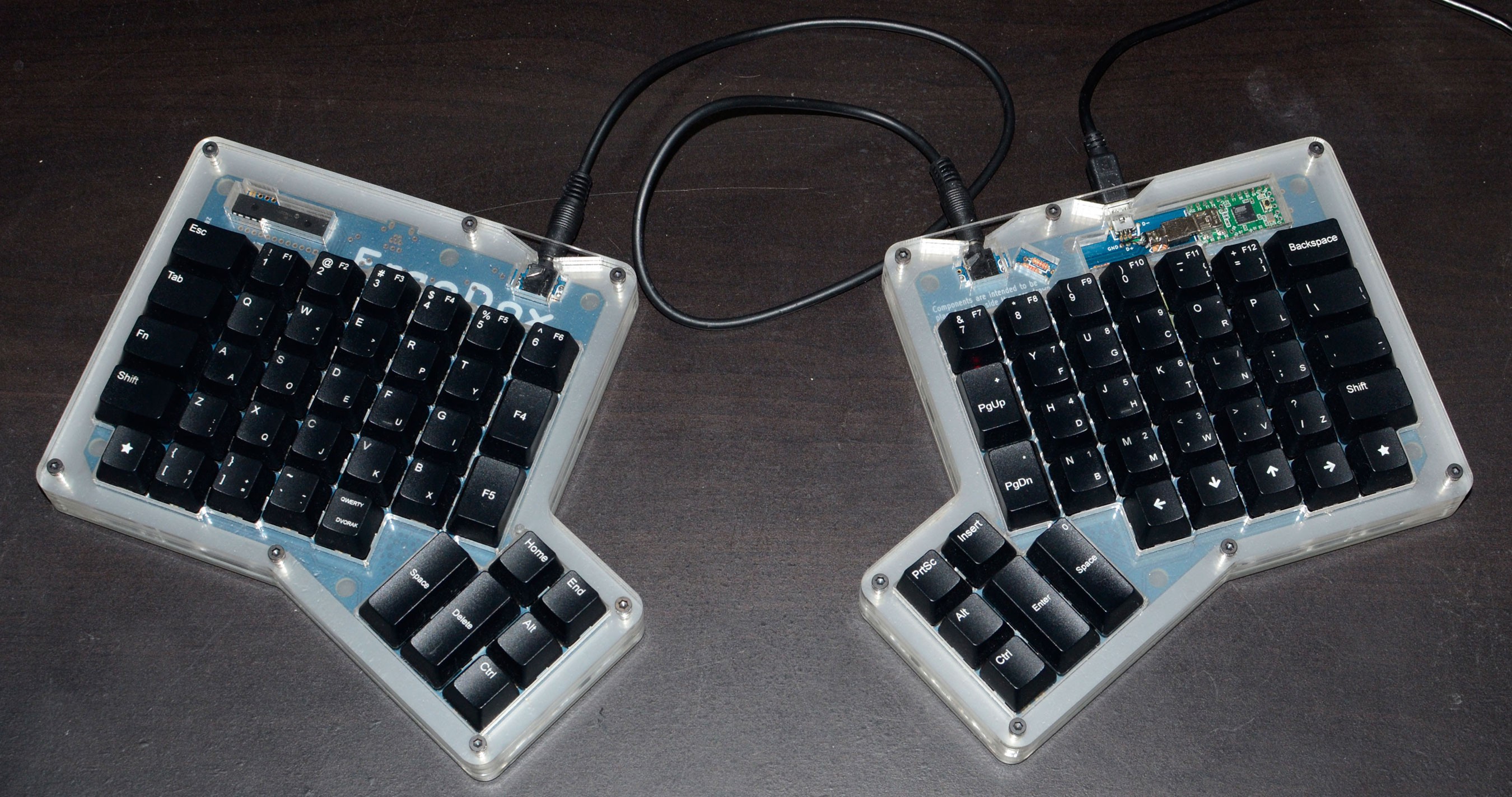
I thought this was amazing. I could make my own layout using the Massdrop Configurator, and eventually use the alternative TMK firmware which allowed the media keys to work.
https://keyboard-configurator.massdrop.com/ext/ergodox
https://geekhack.org/index.php?topic=48106.0
It has a matrix layout with each hand completely separated and uses thumb keys instead or relegating two perfectly good thumbs to one giant space bar.
There are a couple of things I didn't like about it though. I got the "classic" Lister case rather than the "full-hand" one which meant my wrists were completely unsupported and quickly became sore. The two halves were so light that they kept sliding around my desk - partially solved by sticking 5mm neoprene strips to the bottom. The thumb clusters are just a couple of mm too close to the main cluster for my hand to be comfortable. It also annoyed me that it was a fairly expensive kit which required a fair amount of skills to put together.
I thought I could do better and decided to have a go at making one myself.
The differences I wanted were:
- Unibody design instead of two halves. I tend to move around a lot so having both hands at a known place relative to the other is nice.
- Slightly different spacing for the thumb clusters.
- Cheaper and easier for a novice to build.
- Cheaper and easier for production runs.
- Support for more options such as Matias/Cherry switches, LED backlighting.
By this point I was starting to get familiar with the GeekHack and Deskthority forums which are chock full of information on every aspect of keyboard customisation.
That's where I saw people making wierd and wonderful keyboards of various shapes and sizes, though most of them seemed too expensive, too many buttons, too few buttons, wrong shape, etc for my use.
I measured up the ED and realised I could represent the shape of the key postions with a few parameters so I wrote a Python script to plot this out using matplotlib.
I found it very satisfying to be able to tweak some numbers and see the shape change to be more "just right" for me. Although I hadn't made my own keyboard from scratch yet I knew that some people like myself will never be fully happy with an existing design but would love to take an existing design and modify it to be our own.
The scripted, design process using parameters was not going to be replaced by a CAD package with a slick GUI.
Case
Once I had used my Python script (mcdox_coords.py) to determine where the switches should be I needed some way of making that a reality. I eventually decided on building a Shapeoko2 CNC machine to cut out the pattern from a layer of 3mm acrylic.
Acrylic was chosen because it can be quite easy to work with and I had seen it used already in the ED and various other projects on GH. One thing I didn't realise about acrylic is that there are two types sold and are virtually indistinguishable to look at: cast and extruded. This turns out to be very important for CNC milling, although is not an issue for laser cutting.
Cast acrylic mills very nicely creating lots of chips which fire all over the dining room to be hoovered up later.
Extruded acrylic melts when the endmill touches it and the microscopic strands wrap round the endmill bending and breaking it, but not before firing hot globs of melted plastic all over the dining room to sticking to everything and burning your skin.
If you want to CNC acylic make sure, for the love of body hair, that it is CAST. It is possible to very slowly mill extruded acrylic but it is ugly and slow, and error prone.
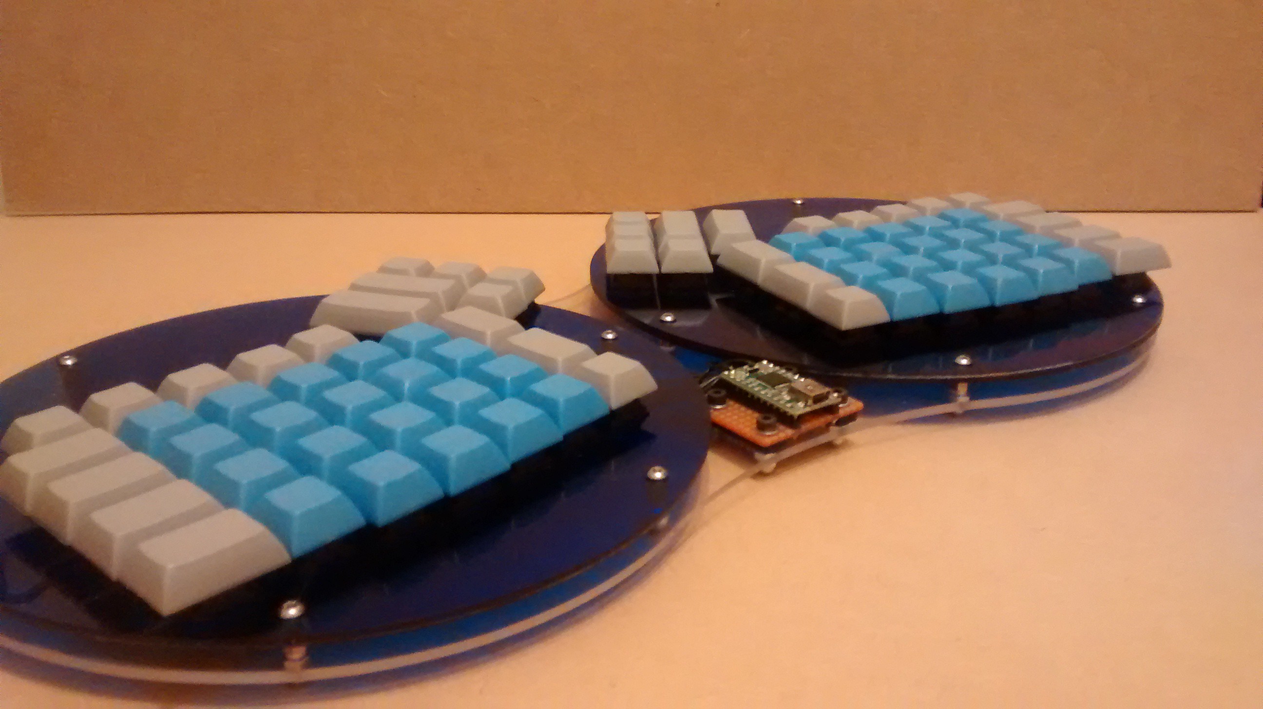
I did eventually get my first prototype case cut as a circlular switch mounting plate for each hand, and a base to hold it all together.
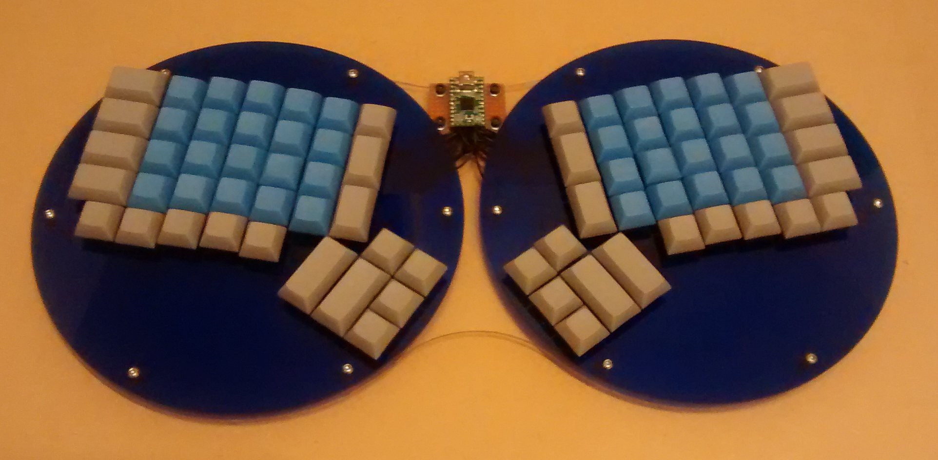
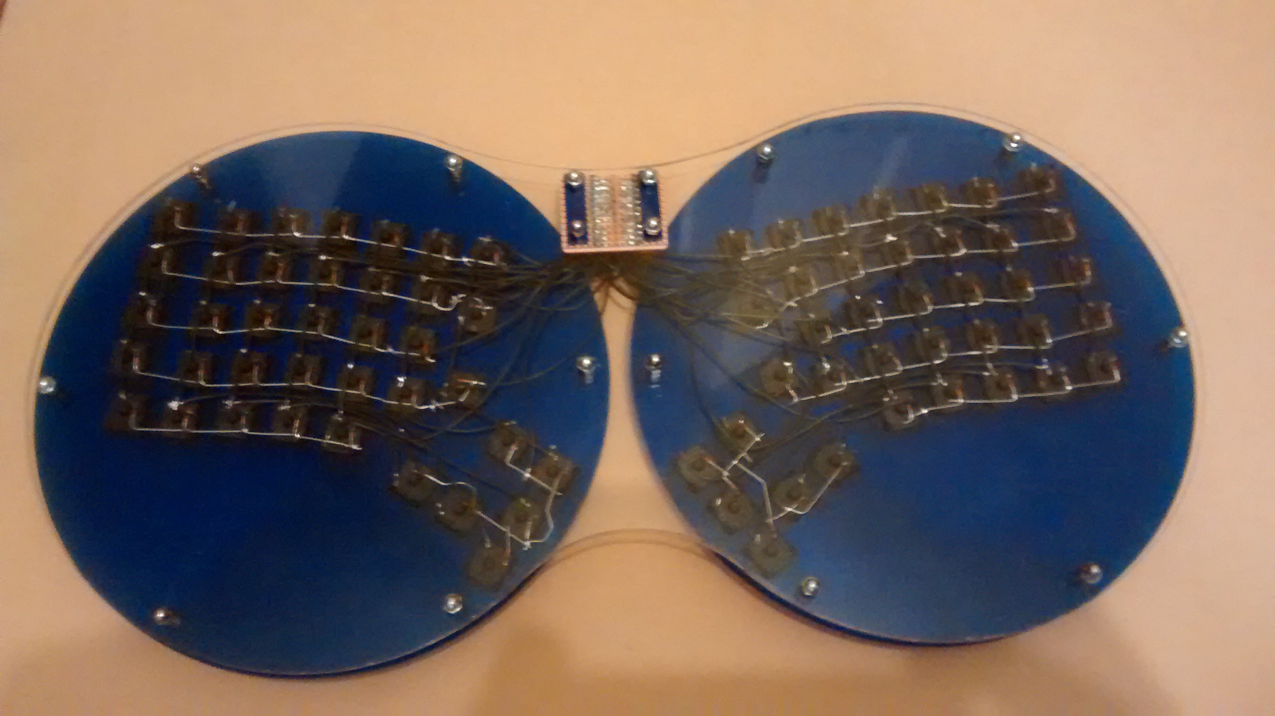
As you can see I didn't have a PCB at this point so all the wiring was done the hard way. This was intentional as if I found the position of a switch to be a bit off then I'd need a whole new PCB, and to really get good feedback I'd have to use it for a few months. I didn't expect the wiring of this method to quite so difficult or time consuming but it took about 6 hours, and I'm an experienced builder. For that reason I wanted to make sure that I and others shoudn't have to deal with that again - More on that in the PCB section.
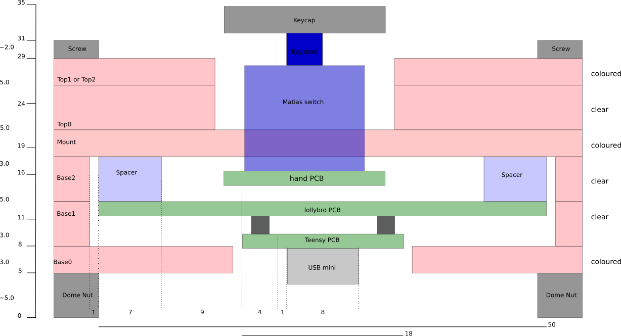
When I'd been using my Mark1 for a while and started to design a real case I initially went with layers the same thickness as the Lister design which uses 2mm, 3mm, and 4mm layers. Then I realised that few acrylic suppliers use anything other than 3mm and 5mm so using the non-standard 2mm and 4mm thicknesses would reduce the list of potential suppliers and increase the cost. I made a mostly scale diagram of the layers in Inkscape to convince myself of the best thicknesses.
I liked the shape of the Mark1 too as it was quite distinctive but simple. One thing about the shape that I knew needed to change was that the outer most keys (Esc and /) protruded just past the edge of the circle meaning that putting it in a bag unseated those keys. The keys at the edge needed a little protection by the case.
So I duly created a design closely resembling the Mark1 with a Python script which spat out DXF files for the laser cutter my friend has. It was just a passing comment about the size that forced a rethink.
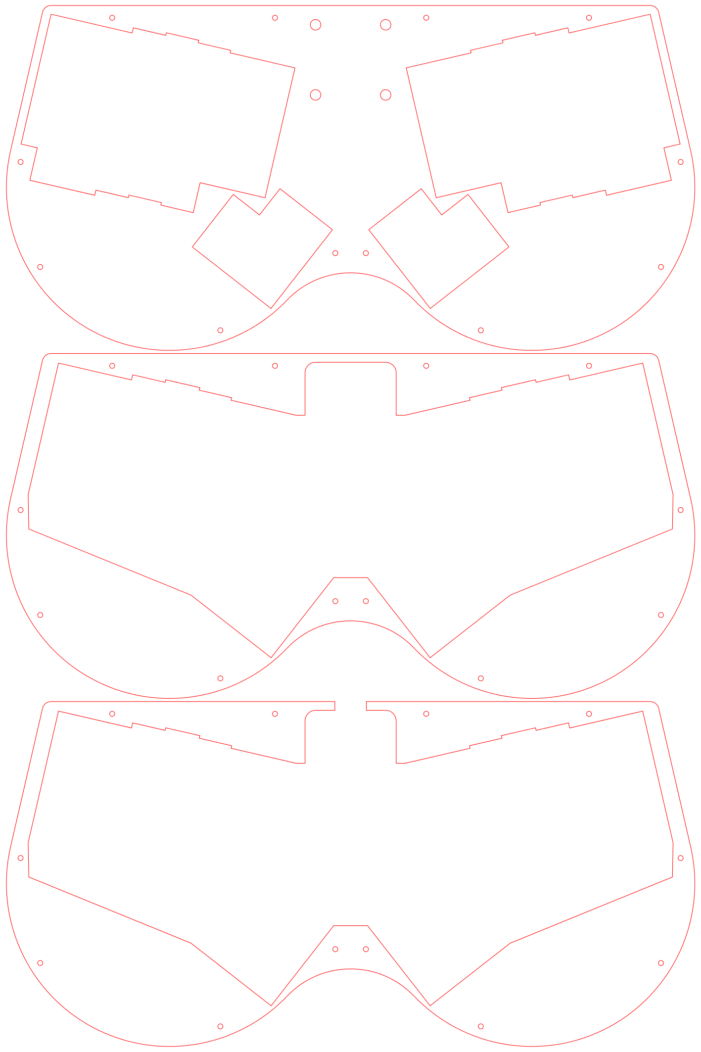
Smaller laser cutters commonly use the size 600x400mm, so for a hackspace or small time laser cutter this case would have to fit in that footprint. In order to save on material for cutting just one keyboard all the layers would have to use as few sheets as possible. This also saves on cutting time too as loading and unloading the cutter isn't exactly instantaneous. So the final shape I decided on is just under 200x400mm meaning that only one sheet each of 3mm and 5mm is needed.
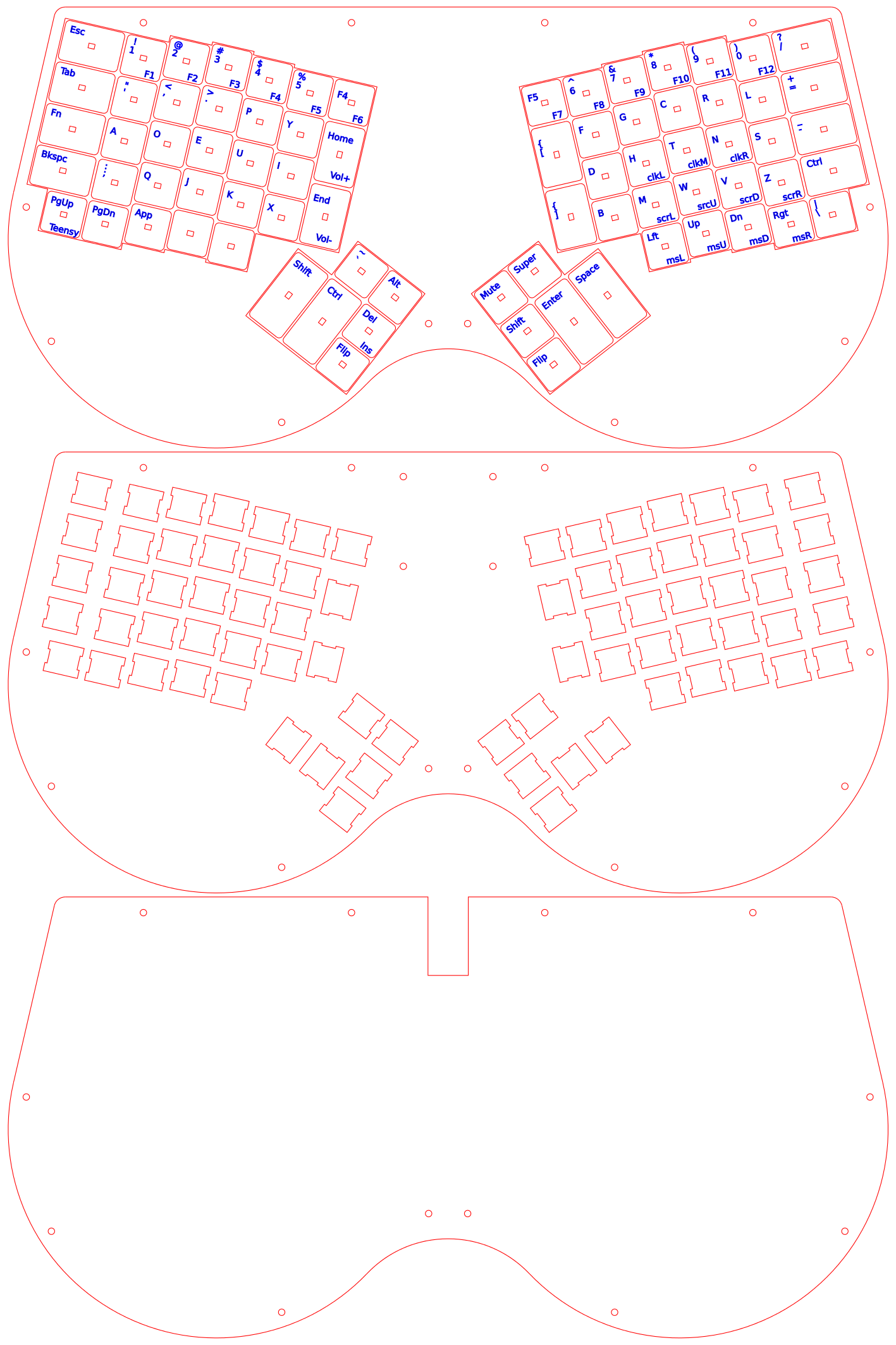
Above is the cutting pattern for the 3mm sheet. As standard, red means cut, blue means vector engrave, and black means raster engrave (no black in this pattern).
There are two ways to generate this, either for CherryMX switch mounts (shown above), or Matias ALPS mounts. You may notice that I used this pattern to experiment with cutting/engraving my own keycaps for Matias switches, despite the middle layer being specific to CherryMX.
Below is the cutting pattern for the 5mm sheet.
Providing the correct file format for different cutters was particularly annoying. To begin with I was using the Python library called DXFWrite since I knew it was compatible with my friend's Epilog cutter. However, it turns out DXF can mean many similar, but incompatible things meaning that I couldn't edit the DXF files directly using any of the free tools available, including LibreCAD. I could use most of them to view what I'd generated though. Eventually, I stumbled across the Lasersaur project (an open source laser cutter) which uses SVG as it's preferred format and looks like it would be ideal for hackspaces.
That made me realise that SVG was probably to better format to generate, and I could post-process it in Inkscape, then convert to whatever format each laser cutter required. The cutters at University of West of England Centre for Fine Print Research, where I got the Mark2 cut were not happy with DXF but were okay with EPS. The pros and cons of different vector graphic file formats is an entire discussion on it's own but I found that Inkscape does a good enough job of conversion that eventually I didn't have to worry too much.
In total, an individual getting a single case cut in the UK can expect to pay about 30 GBP.
- 1 x 600x400 acrylic sheet 3mm: 7 GBP
- 1 x 600x400 acrylic sheet 5mm: 8 GBP
- Cutting time 1 GBP/min: 15
The raw files are generated by my mcdox_svg.py script and post-processed in Inkscape.
I'll talk about the integrated keycaps (from the 3mm pattern) for ALPS switches in the keycaps section.
Hand PCB
By the time I'd started thinking about designing a PCB I knew almost exactly what I wanted.
- The initial placement of switches had to be generated with the same piece of Python I used to generate the case. This would allow me to change it easily when I wanted to make small changes to the case.
- It had to use a plain text data format so I could diff things easily on Github.
- This also made the generation easier.
- It had to be double sided so that it was cheaper in small runs. The cheap'n'dirty Chinese manufacturers like Seeedstudio and DirtyPCBs get much more expensive as you go bigger.
- It had to support some sort of backlight. I'm not too fussed about the gimmik of fancy light shows, but real functional improvements which look pretty are good. Therefore I'm non-plussed about RGB support so one fixed colour of LED is fine.
- It had to support multiple types for each component. Diodes should be either surface mount for production runs, or through hole for an indvidual. Switch hole should be compatible with both CherryMX (most common) and Matias ALPS (cheaper and, in my opinion, a much better switch). LEDs should be embedded SMD like CherryMX RGB variant, or thru-hole in switch like common CherryMX, or shine-through with either SMD or thru-hole for Matias.
- It had to be cuttable. This is the point I decided on after the rats nest of hand-wiring the Mark1 matrix. By making it easy to hand-cut the PCB it is easier to experiment with case mods.
- It had to not require a case.
- It had to be easy to connect to the controller. Like idiot proof, because debugging matrix mis-wiring is a massive pain. I know this from the Mark1.
This seemed like a lot to ask but I eventually found KiCAD's S-Expression file format (and the old format) which is pretty easy to generate as plain text.
I created a "module" containing the various solder points (for cutting/reconnecting), switch pins, switch mounting holes, diode pins, LED pins, LED hole, and the common wiring between them. I could then paste this module everywhere there was supposed to be a switch and I'd only have to do the routing to the connector. It worked quite well once I'd decided on a pinout for the connector and a routing strategy which matched. The only problem was that KiCAD's DRC checker went mad because of all the stuff in the module. I figured that the wiring in the module was saving me more time than it would take to just check everything manually. This was an exercise in extreme attention to detail! Thankfully it paid off and I got 5 working PCBs back from Seeedstudio first time.
I chose to use a standard 26-core IDC cable for the connector to the controller as these are cheap and connect very easily. For my Mark2 I split this into 2x13-core cables since I didn't yet need to backlighting at work. The next improvement I intend to do is change the connectors to 2 USB-C cables which have 16 cores each, in a blatant hacky abuse of the USB standard. Although this would use short USB-C cables internally which do not use the USB protocol, these shouldn't be visible externally to confuse the user.
There are 4 mounting holes per hand which are not used in the Mark2 case. These are intended to be used in either injection-moulded cases with mounting posts, or PCB spacer "legs" commonly seen in prototypes.
The traces are 0.15mm (6 mil) to make the routing easier. This is probably a bit small for home etching but I decided that since there are over 200 holes including vias that home manufacture of the PCBs is not a realistic option. Getting them made by Seeedstudio cost me about 60GBP for 5 hand PCBs.
[TODO pictures]
Controller
The ErgoDox project uses a Teensy2.0 as the controller so since I was basing the mcdox on that I decided to stick with it and just make minimal changes to the firmware.
On the Mark1 the mounting/breakout board was a simple piece of stripboard but wiring was quite messy and error prone - Not the sort of thing I want to do again. So I designed the "lollybrd" mounting/breakout board which is very cheap to get from Seeedstudio (13GBP inc shipping for 10 boards). I used the normal KiCAD processes and DRC for this since it didn't have anything weird like the modules on the hand PCB, and my girlfriend Lolly laid it out so nicely :)
The next revision I intend to make will use the Adafruit Bluefruit Feather Bluetooth instead of a Teensy2.0 to allow it to be wireless. The revision after that will likely be a substantial redesign away from the simple breakout-and-not-much-more style of the lollybrd.
Ultimately, the features I'm aiming for are:
- Bluetooth, reverting to USB when possible
- Battery powered, reverting to USB when possible
- Charge battery from USB, firmware should be able to report charge status
- Built in USB hub
- microUSB port, as opposed to miniUSB or built in cable
- Single colour LED matrix backlight with dimming per LED
- 2 layer, 50x50mm PCB for cheap manufacture
Keycaps
So far, I have just bought these from PimpMyKeyboard who are based in the USA but they are very expensive, especially when the import tax 20%, Post Office handling fee 8GBP, and whatever other charges HMRC take the piss with. PMK do however do ready made keysets for the ErgoDox which is handy.
For CherryMX caps I have found Delvin who are based in the UK and although they have a minimum order of 50GBP the cost is much more reasonable. For my next revision I intend to replace the 4 2.0u caps in the thumb clusters with 1.5u caps and Delvin's pricing scheme seems to fit that nicely. You'll have to call them up for details.
I intend to 3D print an injection mold for CherryMX and Matias ALPS caps for use on a desktop injection molding machine. TODO
Firmware
I started with cub-ubanic's port of the TMK keyboard firmware for the ErgoDox and modified the matrix scanning functions to use my pinout instead. This will require some further work to support new revisions of the controller.
Conclusion
[TODO]
I used the Mark1 for a few months, and I've been using the Mark2 for about a year now so I think I have some good feedback for the Mark3.
My current list of things which I want to improve are:
Use 2mm aluminium instead of 3mm acrylic. It isn't quite as easy to find but not too difficult either and the reduction in height would make the aesthetics better. An aluminium top layer would also make the ugly washers completely unnecessary.
Replace the 2.0u thumb caps with 1.5u. This will make it easier to reach certain combinations, and reduce complexity of keycap molding.
More... TODO