 Atheros
The idea
So, I got this idea to build a clock from Back To The Future movies. Seems pretty easy and inocent, right? Well, I though so too, until I started looking for what I need... But before that I decided to throw in some additional features, like alarm clock and FM radio. I can think of lots of additional features for this build, but I don't think I have enough time for anything more.
Things I need
Once I started to have a general idea of what I want, I started to look at the list of things I need to find. This is how it looks:
- 10x red 7 segment displays
- 10x green 7 segment displays
- 10x yellow 7 segment displays
- 3x red 14/16 segment displays
- 3x green 14/16 segment displays
- 3x yellow 14/16 segment displays
- 12 LEDs (or more)
- realtime clock
- FM radio module
- audio amplifier (mono or stereo)
- 1 or 2 loud speakers
- keypad
- some additional buttons
- potentiometer or encoder to handle volume
- lots of LED or display drivers to handle >350 individual LED lights and LED display segments
- a microcontroller or more to handle all that mess
- lots of additional electronic components (a few hundred resistors for example)
- metal case to house all the components
- lots of workshop tools
- lots of free time
- some money to buy all of the above
When I decided to start this project, I was unaware how big it is for someone unexperienced as I am, but I'll try my best.
Driving the LED displays
This is the first thing I decided to take care of. A quick search provided me with what seemed to be the anwser for all my problems: MAX7219 - 7 segment LED display driver.
MAX7219
Looking deeper I found out a bit more about it.
Pros:
- drives 8 7-segment displays
- can serially chain more chips to support even more displays
- requires a single resistor to limit current
Cons:
- it supports only Common Anode type displays (see Common Anode vs Common Cathode)
- it is actually quite expensive
- it isn't easy to get the original chip (see this great article)
TM1638
MAX7219 was great, but I got really excited reading about TM1638 chip.
Pros:
- drives both, Common Anode and Common Cathode LED displays!
- drives 10 7-segment displays (so exactly the number I have on a single row)
- key scanner
- it is cheap
Cons:
- delivery from China - from 14 to 45 days
I was really excited about this chip, however the risk of it arriving after Sci-Fi contest ends forced me to choose something else.
What else is there?
There are a few more Maxim drivers, even 16-segment drivers. All difficult to get. I read about some other drivers but I don't think it's worth mentioning them here.
Other than those specialized chips, there are two other stand ways of driving LED displays: BCD to 7 segment decoder and shift registers.
BCD to 7 segment decoder
There are 7448 and 7449 chips able to take a BCD number (4 pins) and directly drive a 7-segment LED display. The idea is quite nice, however it require more IO pins than other solutions and those chips are not very common.
Shift register (the winner)
Welcome the 74595 shift register with output latches. This is the solution I chose to drive all of my displays.
Pros:
- this chip can be found everywere, even in electronics retail shops
- it is very cheap
- can chain any number of this chip driving lots of LEDs
- very easy to handle
- can drive 14 and 16-segment displays exactly the same way it drives 7-segment displays
- can drive Common Anode displays
Cons:
- require a resistor for each LED segment it drives
- you either need lots of those chips or switching power to LED displays to drive an array of displays
- no standard way of connecting the LEDs to it so no standard library
Because I am not scared of soldering and I am a software programmer, using 74hc595 shift register seems to be the best match for me.
A quick breadboard wiring and a proof of concept 2 character display driven by two shift registers and an arduino shows I can do simple electronics :)
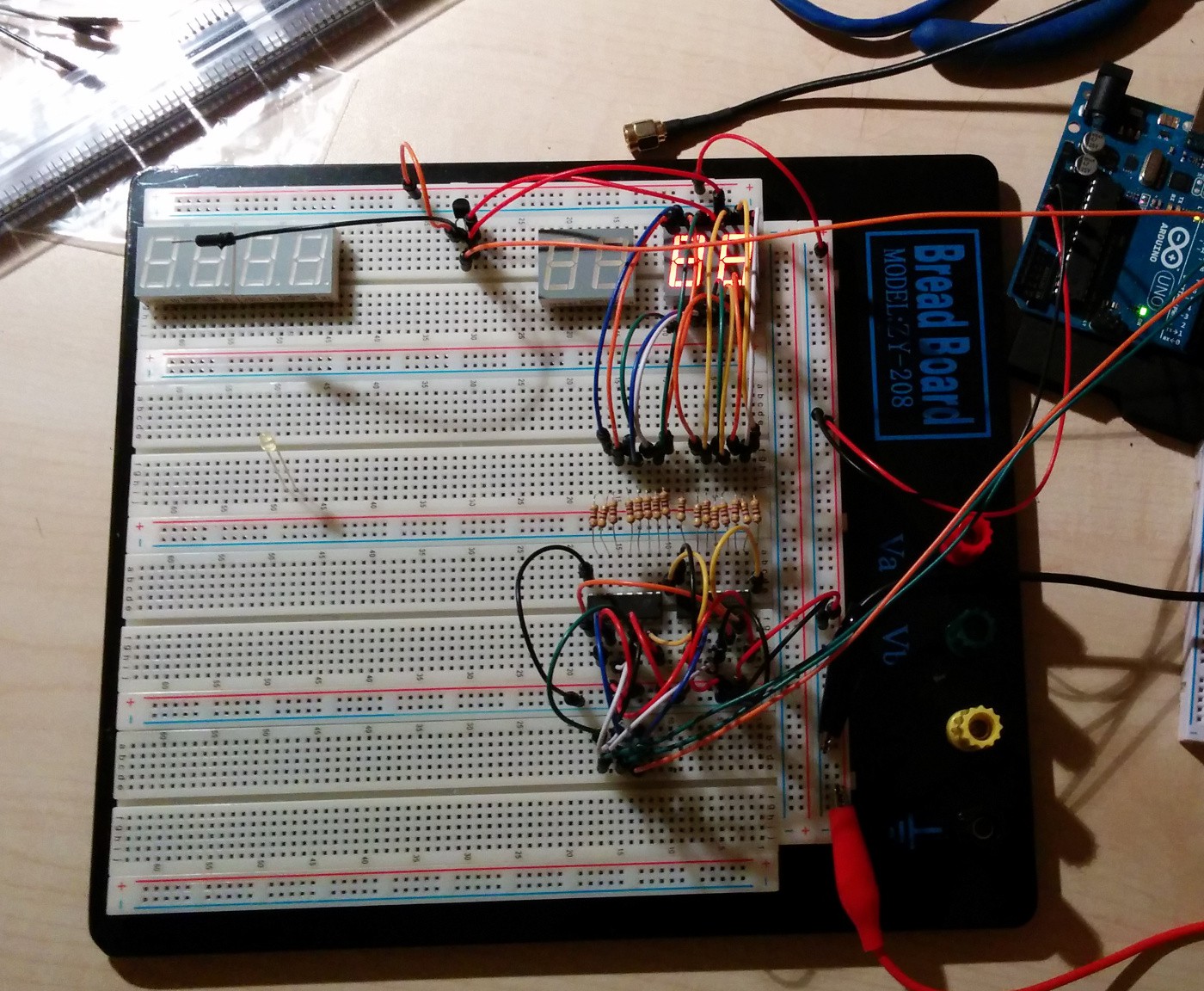
(if you notice the transistor used for PWM driving is badly connect, please ignore it...)
Common Anode vs Common Cathode
I though this question is of little importance at first, and maybe for many people and projects it is. However I found two very important differences between them:
- not all driving methods supports both types of displays
- not all types of displays are available in all colors
- not all sizes (character height) are available in all packages (single, 2 chars, 3 chars or 4 chars), colors and types...
It looks like LED displays are a thing of the past. Sure, why would anyone want to mess with all those pins, additional expensive or comples drivers if there are all those cheap serial LCD displays that can display a lot more? My advice to everyone wanting to make something with LED displays, find the displays first, then worry about driving them.
Conclusion
After a week or more of research, I feel really tired. More than once I thought I have all figured out and then I had to rethink everything. But I think I made some progress.
These are the things I am certain of and hopefully won't change:
- I will be using shift registers (74hc595) to drive the LED displays
- I will be using kingbright displays with common anode (already ordered)
- 7-segment displays in dual character packages, 0.56" character height
- 14-segment displays in dual character packages, 0.54" character height (I notice the size differenace...)
What next?
There is already some more progress or some failed tests if you prefere. I'll write more about it in the next update (including some photos).
Now I will be doing to the following things:
- design and build a first display board for year display (as it is the simplest one)
- build display boards for all other 7-segment displays
- build month display board (with 14-segment displays)
At each step I'll try to post some progress reports, so stay tuned :)
Discussions
Become a Hackaday.io Member
Create an account to leave a comment. Already have an account? Log In.