 Michael Skrepsky
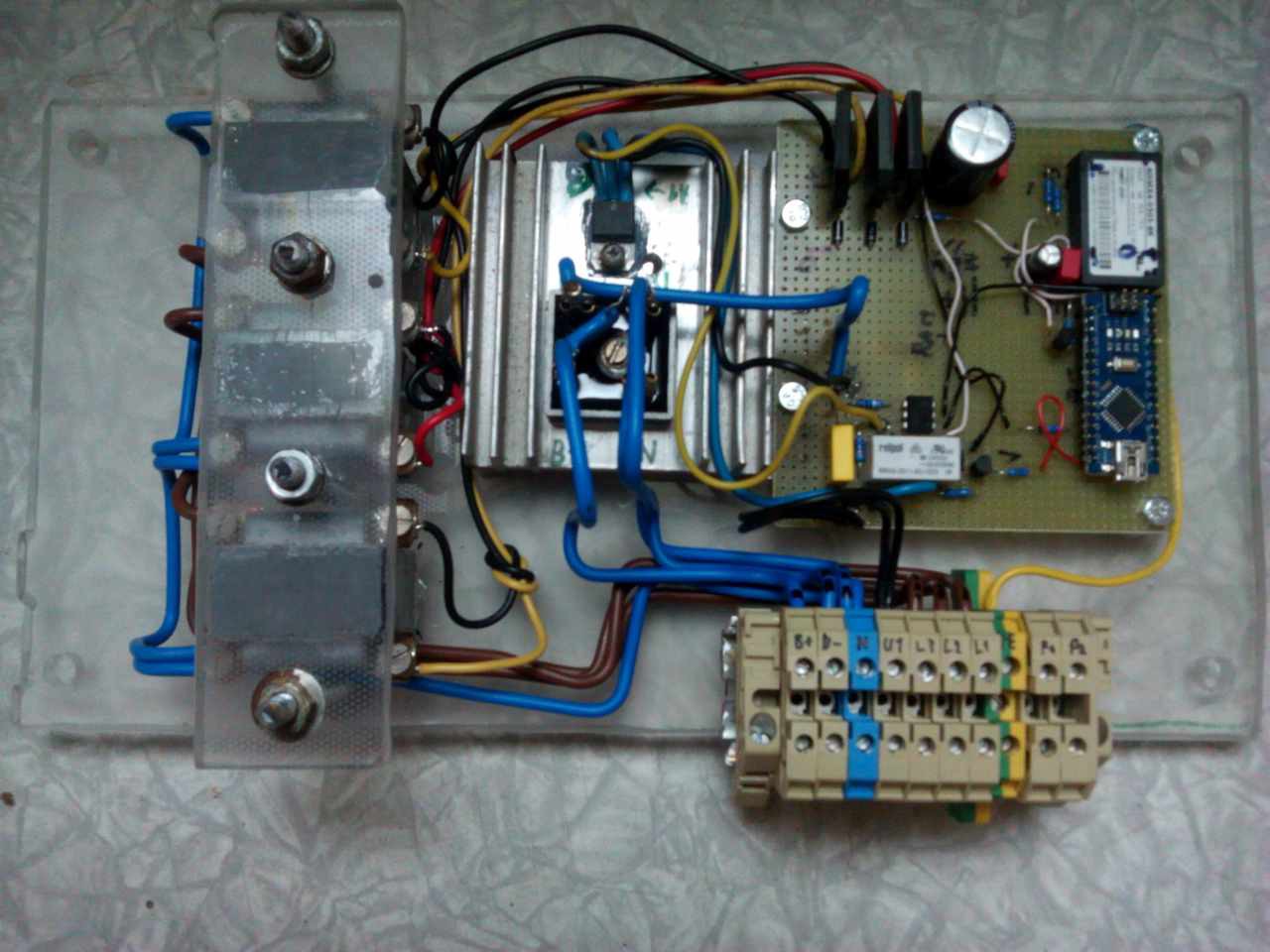
I needed to replace old voltage regulator for my old diesel generator, that i bought very cheap in a bad shape as something to play with. I tried to repair the old regulator, but after tens of loose contact repairs, bad component replacements i gave it. It was destroyed by mice, corrosion, vibrations and previous owner's attemts to repair it.
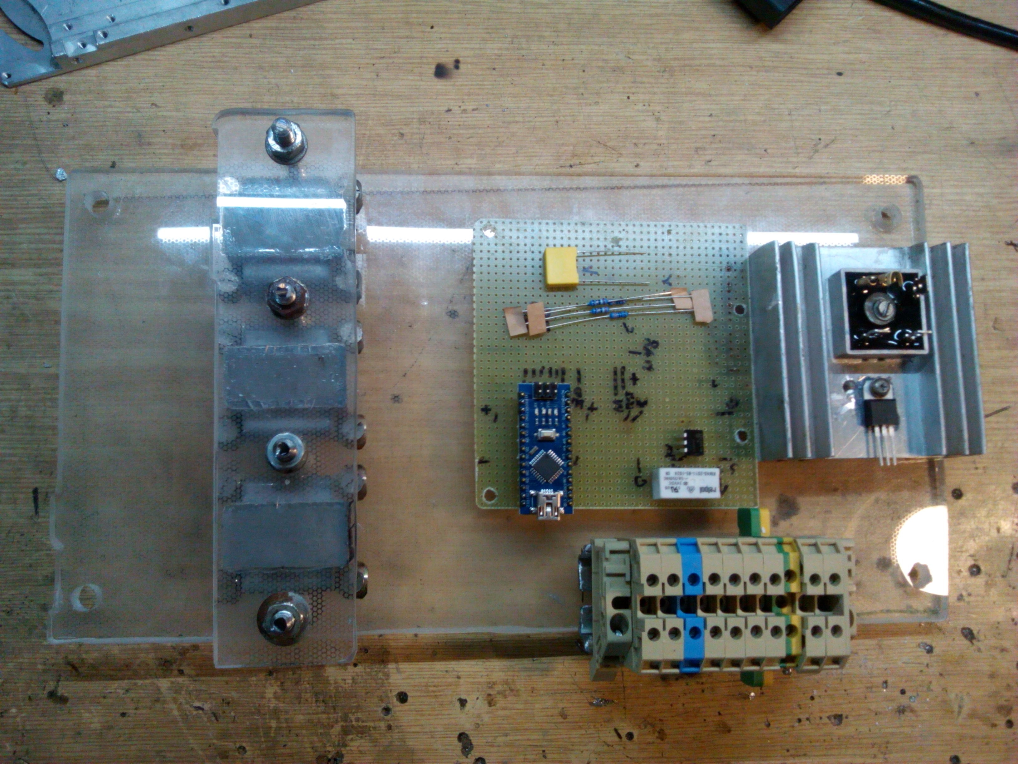
The new regulator will be as simple as possible and easier to diagnose, repair and adjust. I plan to add functions like throttle control, oil watch, etc., but only after correct voltage regulation.

 electronicsworkshops
 DeepSOIC
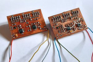
 256byteram
This an interesting project. I am currently working on something similar. I want to stabilize voltage and frequency of an alternator. I envisage to use Arduino uno r3 as a microcontroller. The aim of the project is to built a controller that is is able to quickly respond to load variation and system parameters changes. I am planning to use fuzzy logic as algorithm for the microcontroller. Would you please share with me, how you succeeded to implement yours? What are challenges you encountered? I am also available at asingejack@gmail.com