 Ted Yapo
I found some time to populate one of the the PCBs this evening. The only problem was forgetting to put the USB jack on there before putting it on the skillet. I realized just as the first flux fumes were rising off the board, so pulled it back off to place the jack.
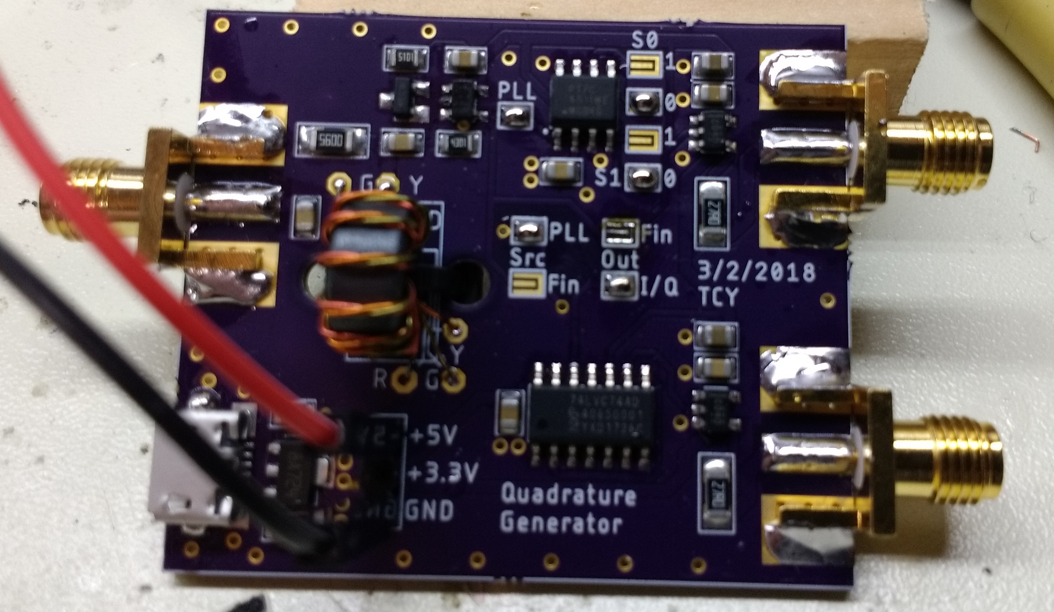
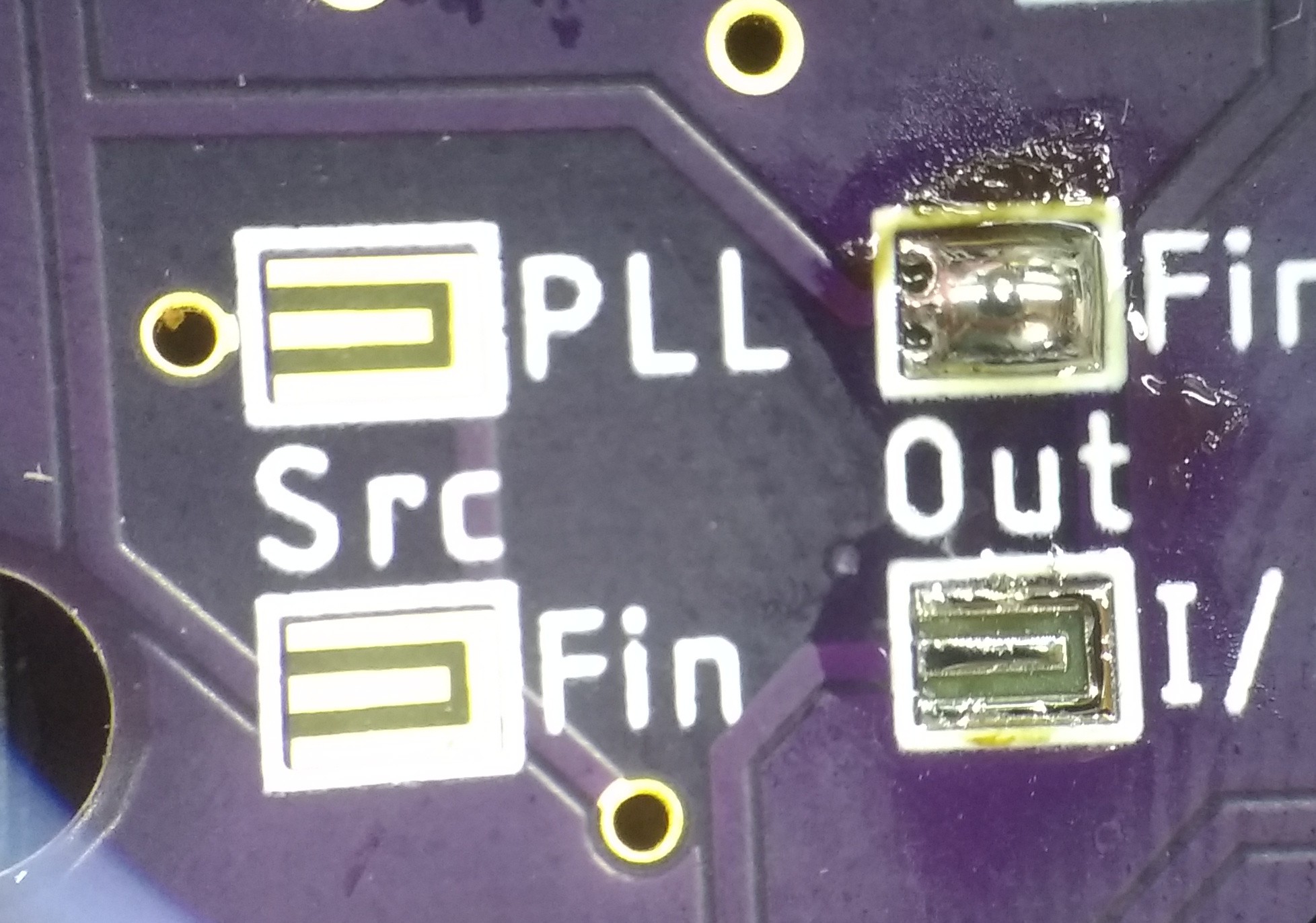
You can see the trifilar-wound input transformer on the left. I originally planned to load 10 turns of wire on the core, but only 8 would fit comfortably. I thought this might affect the low-end response, but it didn't (see below). You can also see the solder-blob programming sites I used instead of zero-ohm jumpers (or DIP headers) to configure the circuit. These worked better than I expected. To short one, you just melt a blob of solder on it, and you can open it back up with solder wick. Very easy to do. You can see them in various states here:
I wouldn't use them for sensitive analog stuff, but for digital lines, they're fine. The one thing I would change is to add thermals when the outer terminal is at ground. I usually don't do thermal reliefs on SMT boards, but the ones surrounded by the ground plane were a little more difficult to solder.
Testing
I tested the PCB by connecting the outputs to a 300 MHz oscilloscope.
Input Buffer
I first hooked the board up so that the output from the input buffer (a 74LVC1G14) was passed directly to one of the output drivers (a 74LVC1G04) so I could test the frequency range. I drove the input from the tracking generator of the DSA815-TG set in zero-span mode. At 1 MHz, the input buffer toggled down to -7 dBm input level, but the waveform symmetry was best above -4 dBm. On the high end, the input buffer was good to 93 MHz when driven at 0 dBm, the maximum output of the tracking generator. I honestly expected this to go higher. When I get a chance, I'll have to dig into it a little bit more.
Quadrature Generation
In this configuration, the input buffer feeds a 4x PLL clock multiplier, then the quadrupled frequency drives a quadrature clock generator made from a 74LVC74 dual flip-flop. Because the I/Q generator divides the frequency by 4, this configuration yields in-phase and quadrature clocks at the same frequency as the input. This mode worked better than expected. Here's the quadrature outputs at 300 kHz, about as low as it will go reliably when driven with 0 dBm input:
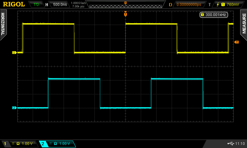
At this frequency, you can start to see a little jitter on the edges. It will actually toggle at lower frequencies, but the jitter becomes progressively worse.
The output is 2V p-p into a 50 ohm load (the scope has a 50-ohm termination mode). That's +13 dBm.
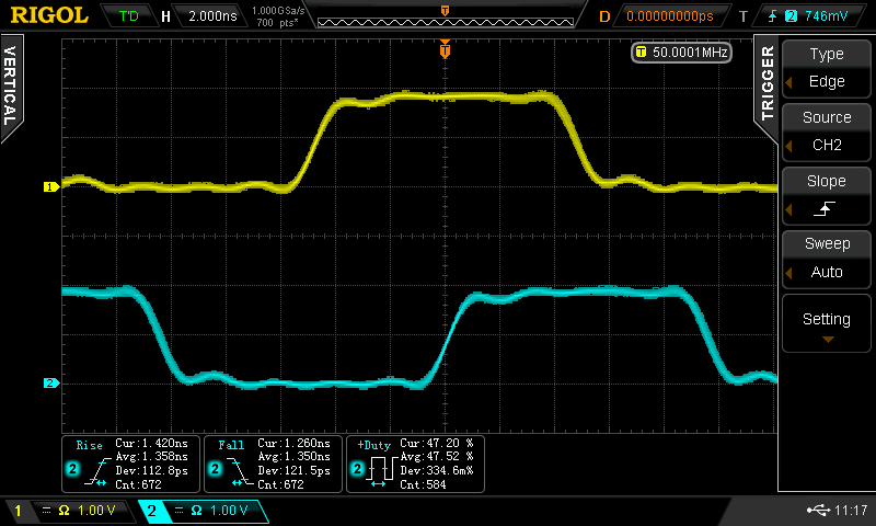
On the high end, it seems to work reliably up to around 70 MHz, shown here:
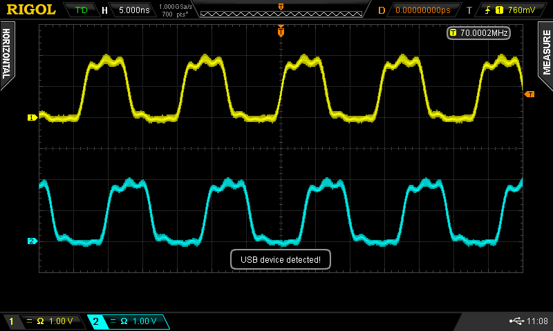
It's only a 300 MHz scope, so looking at the shape of 70 MHz square waves isn't absolutely precise, but they don't look bad. A very odd thing happens above 70 MHz - you can turn the input up to around 90 MHz, but the output sticks at 70 MHz! What's happening is that the PLL's VCO is maxed out at 280 MHz (70x4). That's still very good, since the PT7C4511 is only guaranteed to 180 MHz at 3.3V (200 at 5V). So, you can't count on this performance if you build one, but you might get it. Still, I expected to see a maximum of around 50 MHz at the I/Q outputs, so I'm pretty satisfied.
What this means, though, is that the PLL and the 74LVC74 are both running at 280 MHz. If I wanted a very fast clock, I could just wire one of the output drivers to the PLL output. Unfortunately, I didn't think of this when I designed the PCB. If I make another revision, it's definitely something to add. In the mean time, I still have 2 blank PCBs I could rework to try this out.
I measured the rise and fall time of the output clocks at around 1.35 ns, which is about the rise-time of this scope, so the outputs may be faster.
That's pretty fast, so terminated lines are required for any substantial cable runs, which brings up a problem I didn't see at first.
The outputs are source-terminated with 27-ohm resistors, which I thought would make 50 with the output impedance of the 74LVC1G04s. If this were true, the output peak voltage should be 3.3/2 = 1.65V. Since the output peak voltage is 2.0V, it means the 27-ohm resistors are too small. A little algebra (I won't bore you) shows the output impedance of the drivers plus resistors must be 32.5 Ohms, and the drivers themselves must be 5.5 ohms. This is much lower than I expected. Based on this, I'd need 44.5-Ohm resistors in the output to get a good 50-ohm termination. They make 44.2-ohm 1% resistors, and I probably have some 43-ohm 5% ones around to test. When I get a chance, I'll have to swap them out and see how the output looks.
Power Consumption
I had hoped the circuit would draw less than 100 mA so that it could be run off any USB port. At 1 MHz, I measured 78 mA from the 5V supply, but this rose to 144 mA at 70 MHz. The original idea was to power the PCB from the USB jack on the front of the DSA815. Now, I'm not so sure. 144 mA is definitely out of the USB specification. Maybe I'll use a USB current meter and plug something in there that requests more than 100 mA. If the request is granted, I can assume the DSA815 is capable of supplying that much. I'll have to experiment a bit. I can always power then thing from any one of a dozen USB power supplies around here, too.
Unfortunately, this also means that the 78L33 I'm using to create the 3.3V supply from the 5V input is being abused. It's only rated for 100 mA output. It didn't burn my finger during testing, but this probably isn't a good thing to do long-term. The PCB has a 3-pin header for GND, +3.3 and +5 volts, so I could power it from an external 3.3V supply until I figure out exactly what to do.
Overall, I'm pretty happy with this as a first version. It's definitely usable as-as, although I'd like to get that 280 MHz maximum output frequency working. That would probably be all I would ever need in a lab clock generator. Even as it is, the 70 MHz outputs greatly exceed what I could do with a 25MHz DDS which I was using before.
Discussions
Become a Hackaday.io Member
Create an account to leave a comment. Already have an account? Log In.