 Kris Winer
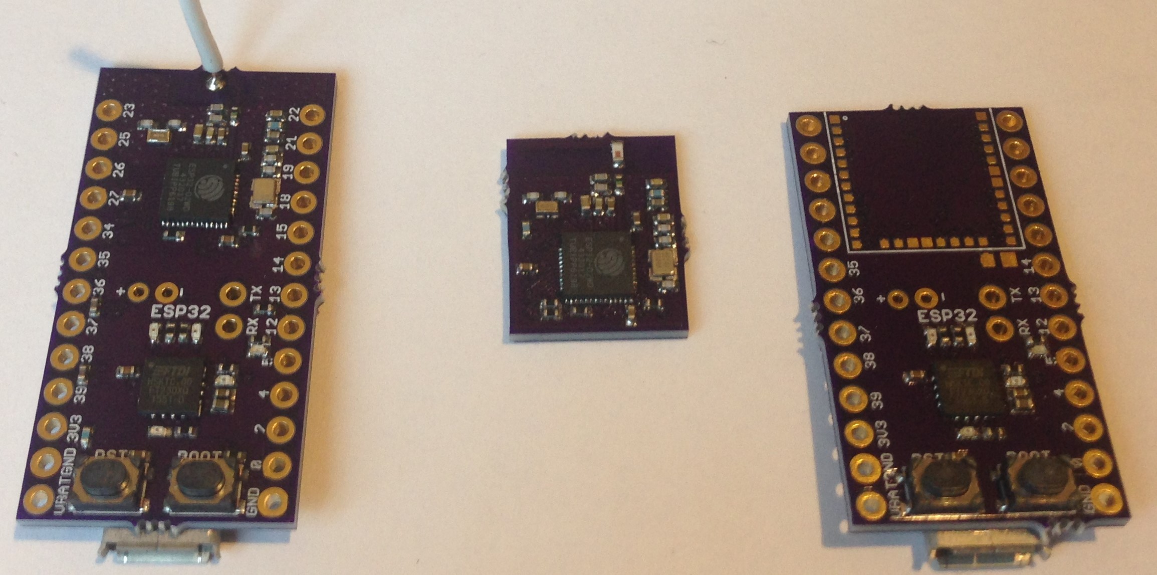
The ESP32 is a promising MCU with concurrent wifi/BLE, two 240 MHz CPUs, a floating point unit, an RTC, and lots more GPIOs than the also-very-useful ESP8266/85. I prefer to design my own circuits rather than use modules but sometimes a well-designed module can speed the prototype process and ease assembly work in custom boards. The commonly used ESP32-WROOM-32 module is one I have used in this way, but I found its size rather gigantic and limiting. I was only able to expose a few of the GPIOs without widening this board even further:
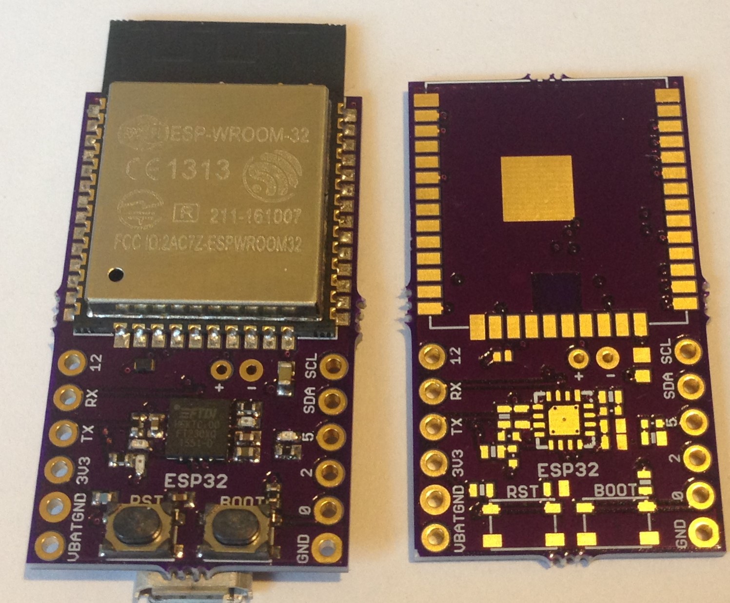 Sensors on the back turn this into a motion sensing utility board intended for pocket wear but the size of the WROOM module plus pads (20 x 26 mm) makes very small board design prohibitive.
The WROOM module is this large partly because of the external SPI flash used for both data storage (via SPIFFS, for example) and program flash. In addition, the WROOM uses the standard 6 mm x 6 mm ESP32 QFN48 package. The WROOM uses connector pads intended to solder to the sides of the module instead of below like the Rigado BMD-350, for example. Lastly, the WROOM is designed with a rather large pcb antenna which takes up a large part of the module length.
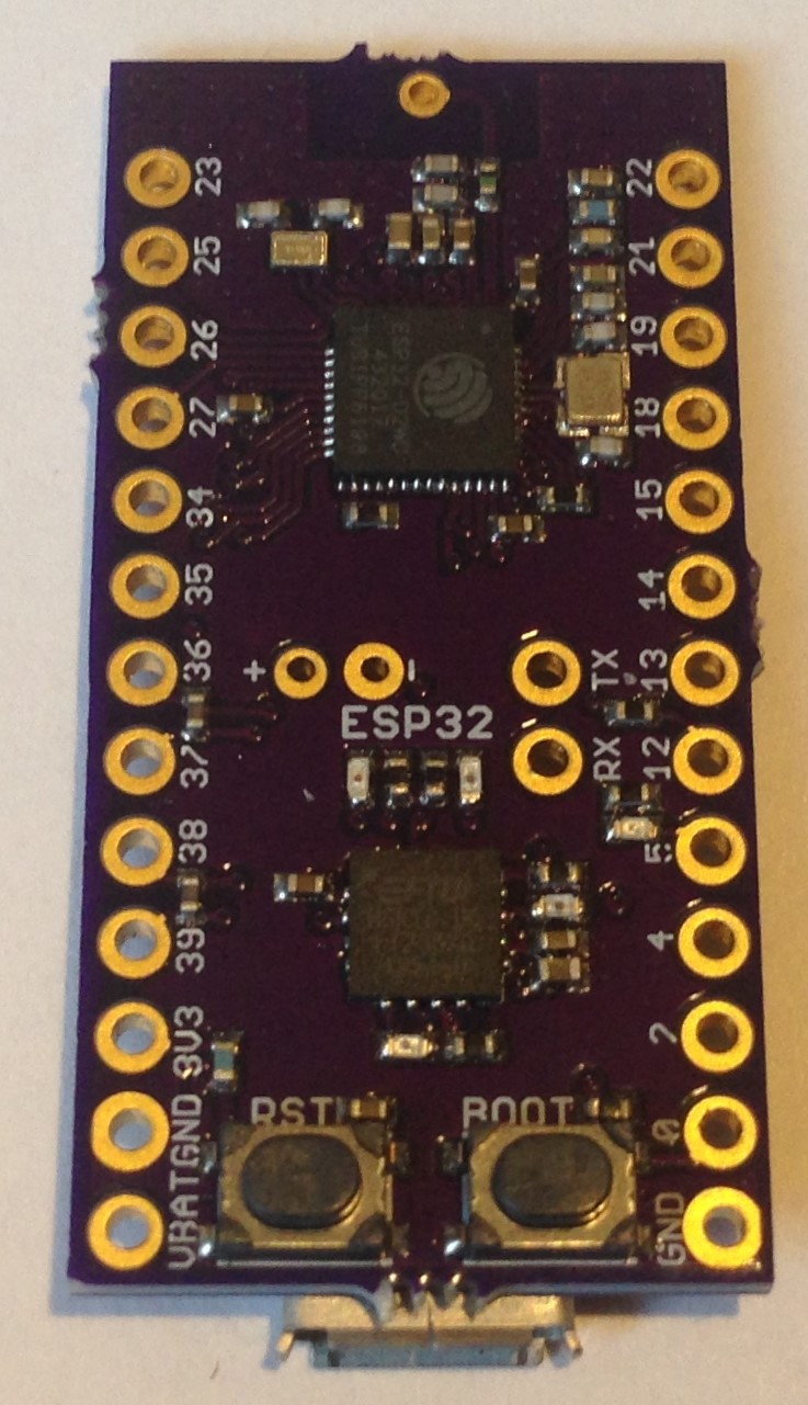
With the advent of the ESP32 D2WD, this can now change. The ESP32 D2WD is embedded with 2 Mbytes SPI flash, so no need for an external flash chip. The ESP32 D2WD is a 5 mm x 5 mm QFN48 package, 69% as large as the standard 6 mm x 6 mm QFN48 ESP32. The combination allows the creation of much smaller ESP32 board and module designs.
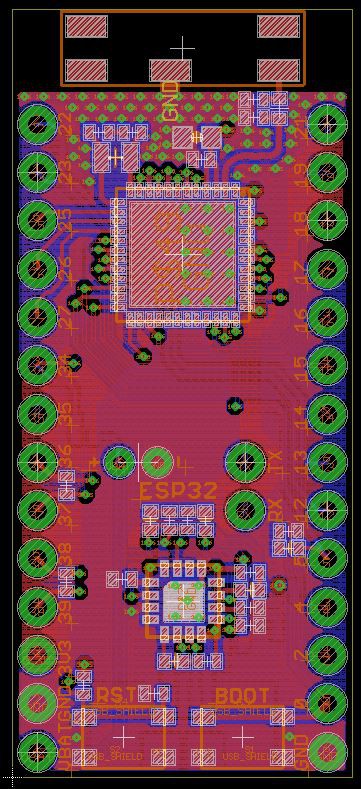
First of all, just the design of a development board using the ESP32 D2WD requires a smaller board area (~12.7 mm x 12.7 mm) for the ESP-specific circuit.
 Upside is smaller ESP32 IC size and no external flash. The downsides include two fewer GPIOs (losing GPIO16 and 17) and much harder hand assembly. The pitch of the pins is a terrifying 0.35 mm, difficult for all but the most expert solder paste slingers.
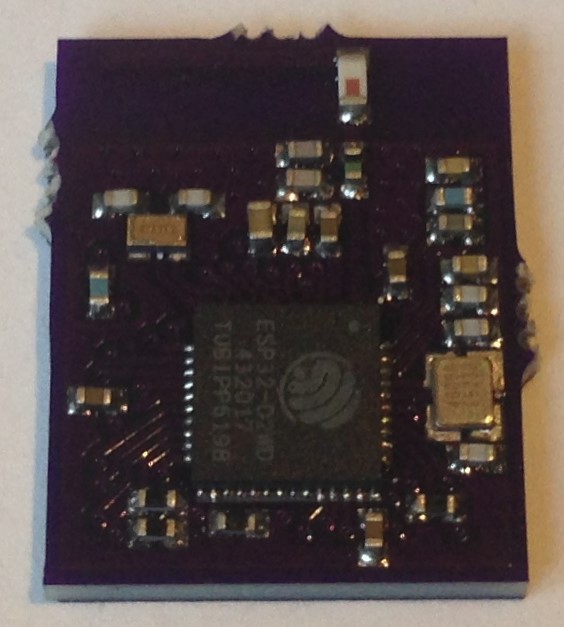
In order to ease the burden of this difficult assembly I designed a small module based on the circuit in the above board. The idea is to have the module manufactured in China at a reasonable cost, and then make use of the module with a much easier soldering process.
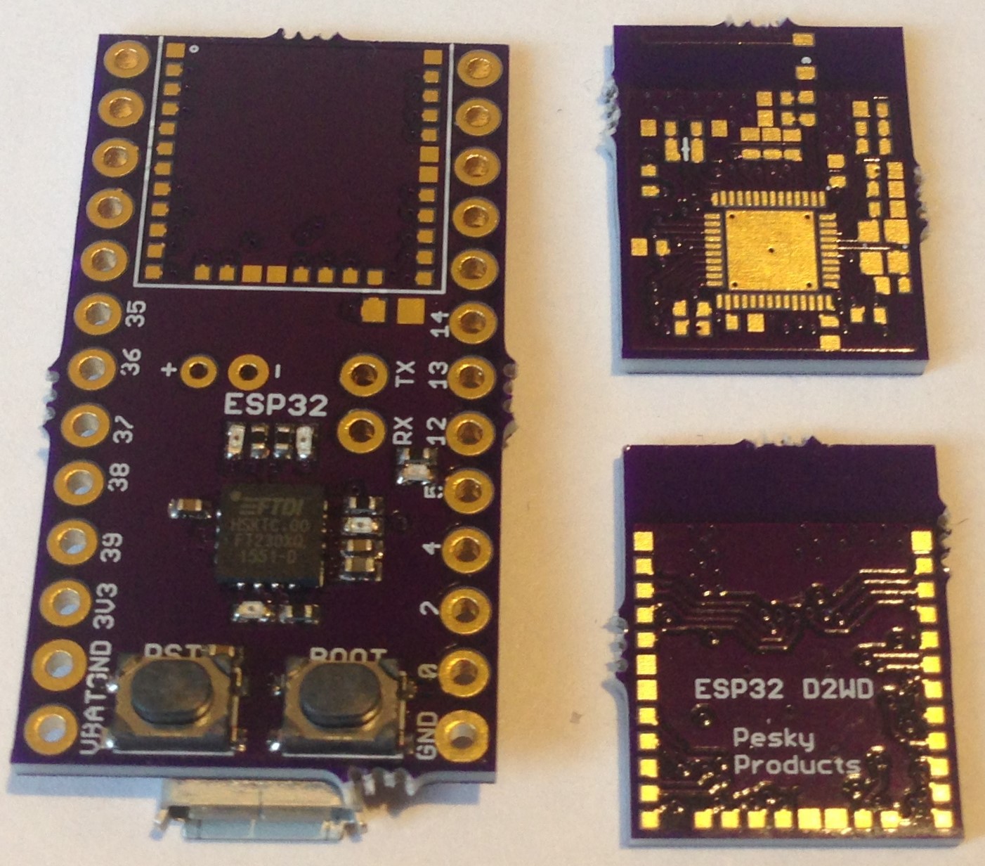
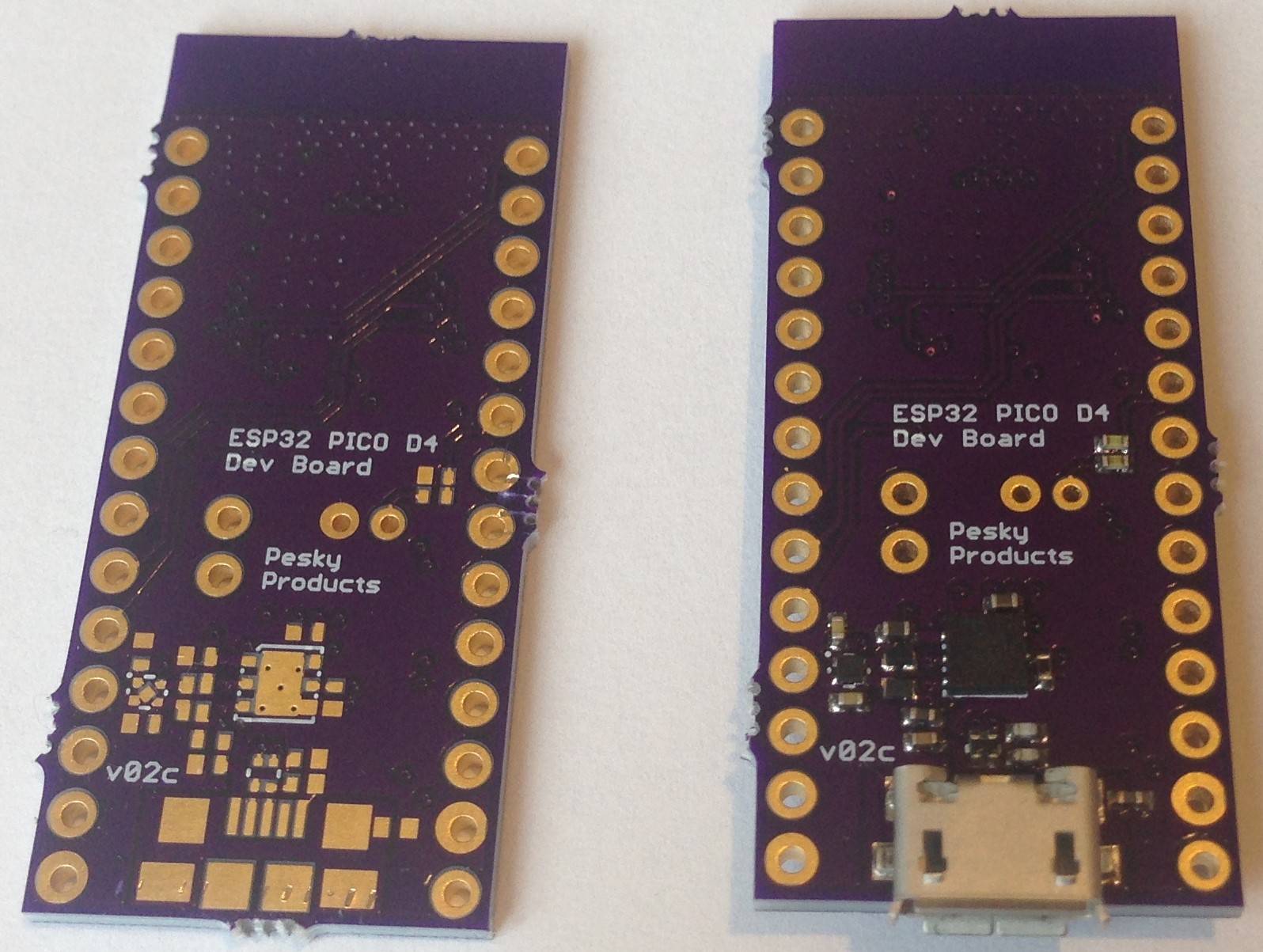
I first captured the ESP32 D2WD circuit onto a 12.7 x 12.7 4-layer pcb, added three mm in length for a chip antenna and designed a reasonable routing of the 24 available GPIOs and 8 power pins to back pads on the board periphery to make mounting using (low-temperature) solder paste and a hot plate/hot-air gun very easy. This is following the soldering strategy Rigado uses for its nRF52 modules like the BMD-350 which I use a lot and find the soldering of the module quick, easy, and reliable. I want the same experience for the ESP32.
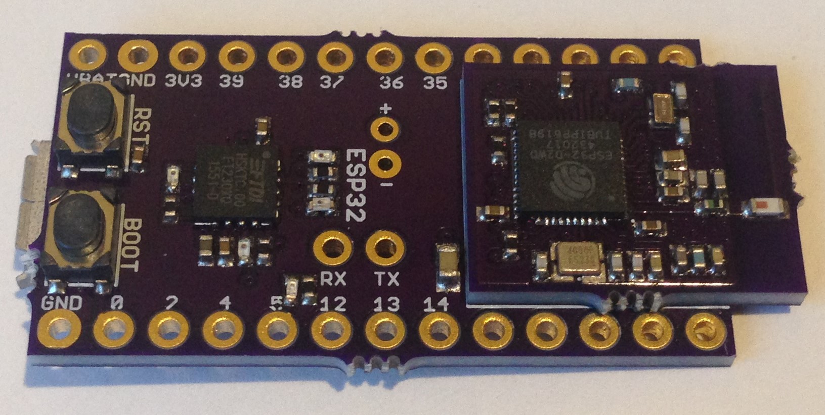
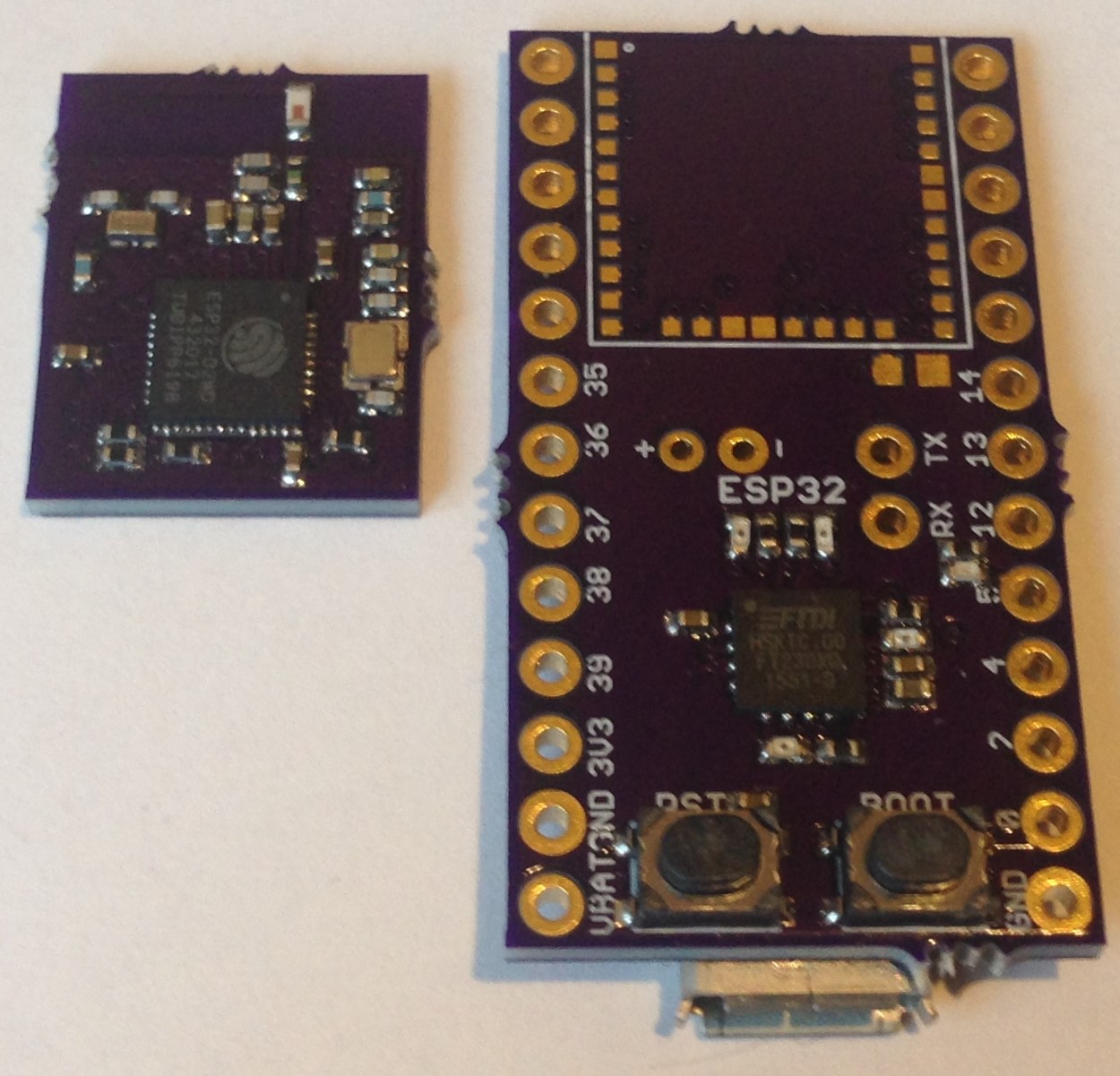
I redesigned the development board into a daughter board to accept the module and I am in the middle of assembling everything and testing the concept.
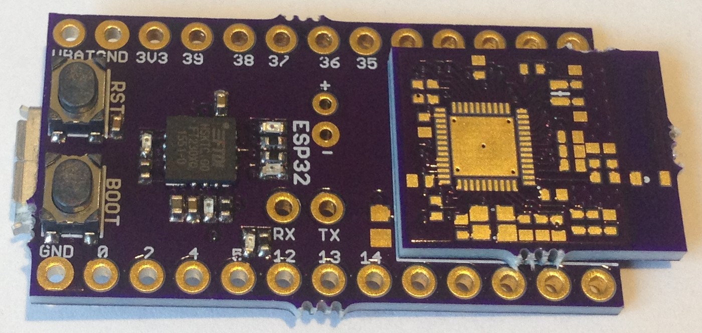
Tomorrow's task is to assemble one or more of the ESP32 modules and then solder them onto the daughter board. The required pullups on nRST, GPIO0, and GPIO12 (the embedded flash runs at 1.8 V, which is why we lose two GPIOs) as well as the pull down on VDD_SDIO are already on the module, so there are fewer passives required on the daughter board. I included the 32.768 kHz (ABS05) crystal and passives on the module since eventually I would like to be able to make use of the RTC clock and sub-processor. I left off the 270 pF capacitors connecting pins 38/39 and 36/37 on the module, of course, but also on the daughter board, I can't remember why. It is easy to remove the caps if these GPIOs are needed for inputs. Maybe with two fewer GPIOs I was thinking touch pins are less useful? I added a 0603 10 uF bulk capacitor on the VCC input to the module for good measure.
There is no guarantee this is going to work, or is going to work well. I have never used this particular type of chip antenna before but I find it hard to believe...
Read more »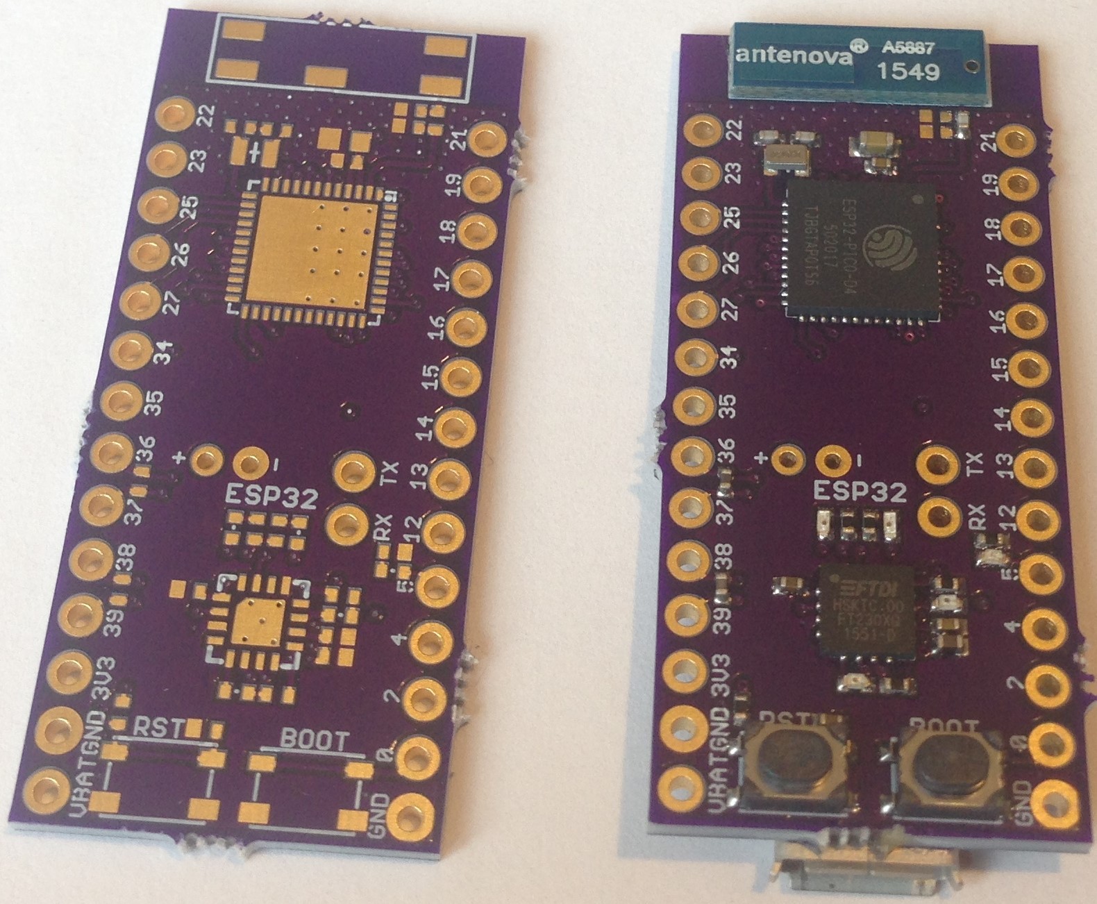


 sparky-p32
 Parnika Gupta
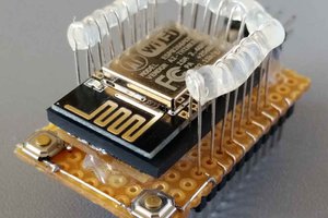
 medeiros1
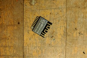
 Sophi Kravitz
I really like the possibility of a smaller yet equally powerful board. Of course, there's always the ESP-WROOM-02 featuring a much smaller size, but ... It just looses a bunch of GPIO.
Good luck! I wouldn't want to solder this myself (that chip size IS daunting), but if you get a few models working that'd be awesome!
EDIT: I didn't realize the ESP-WROOM-02 was only using the ESP8266!
That's a bummer.