 Kris Winer
03/03/18
Just completed Phase 1 of the ESP32 module assembly. The strategy in a nut shell is (Phase 1) to assemble an integrated development board using the ESP32 D2WD and then a module with same, then (Phase 2) solder the module to the acceptor board and (Phase 3) compare performance of the integrated board to the modular board.
Here is the collection of boards at the end of Phase 1:
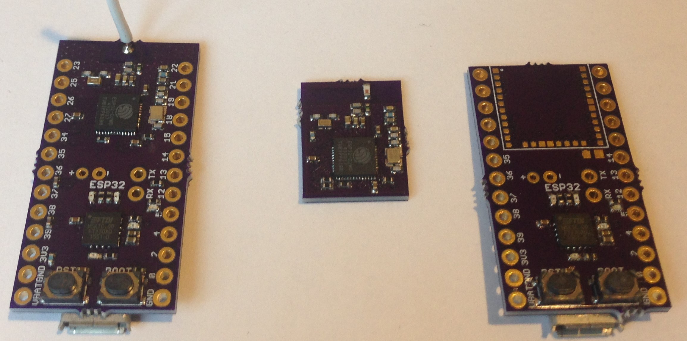
Initial assembly of the two ESP32 ICs and surrounding circuit was reasonably quick but it took me a long time to cure the last of the solder bridges. This 0.35-mm-pitch is tough!
I verified I could flash a blink program (ESP32 Dev Module, QIO, 80 MHz flash speed, 2 MByte flash, 921600 upload speed) onto the integrated board using the Arduino IDE and the led works and I am getting battery voltage and ESP32 IC temperature on the serial monitor as requested. So at least the basic design seems sound and the integrated board works.
I soldered a 1.2-inch copper antenna on the integrated board, which provides adequate reception. One of the things I want to test is the reception of the chip antenna relative to this monopole wire antenna solution.
Here is a close up of the module before I assemble it onto the mother/acceptor board:
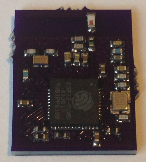
Everything except the ESP32 D2WD itself is easy to assemble. I am using the 40 MHz HSE crystal in this design even though I had used the same 26 MHz crystal in my original ESP32 and ESP8285 development boards. The ESP32 works with the 26 MHz crystal but since the current version of the ESP32 reference design uses 40 MHz so will I.
Next task is to solder the module onto the acceptor board:
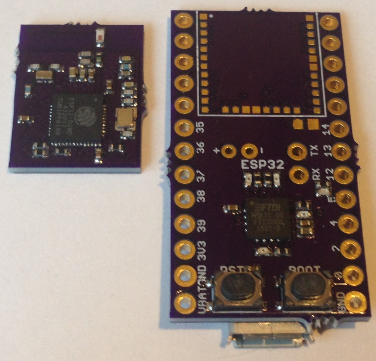
Next, Phase 2...
Discussions
Become a Hackaday.io Member
Create an account to leave a comment. Already have an account? Log In.