 jeromekelty
Yep- I let out the magic smoke. While getting ready to do a test with the radio transmitter I accidentally reversed the power wires to the FemtoBuck and smoked the driver chip. I ordered a replacement AL8805W5 chip, removed the blown one using a hot air tool and soldered the new one in. Note to self- ALWAYS use polarized connectors!
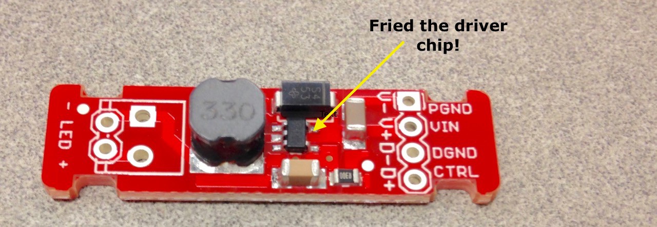
As soon as I was back in business I set about making the RC radio receiver signal work with the FemtoBuck. The FemtoBuck is able to dim the LEDs by applying a voltage range of .5V to 2.5V to its control pin. The problem is that my RC receiver doesn't output a compatible signal so a fix is needed.
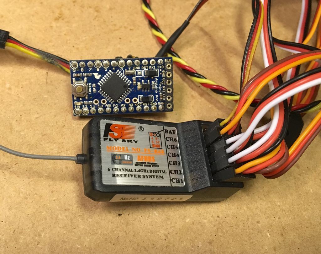
Arduino (Pro Mini) to the rescue! At the beginning of this project I thought I'd finally build something animatronic without an Arduino in it but the little bugger managed to work its way in there...
Using this code the Arduino was able to take the output of the receiver and turn it into something useful-
const int inputPinA = 2; // The pin connected to the RC receiver's servo output A
const int outputPinA = 3; // Output PWM pin A
void setup() {
pinMode(inputPinA, INPUT);
}
void loop() {
unsigned long pulseLength;
pulseLength = constrain(pulseIn(inputPinA, HIGH), 1000, 3000);
analogWrite(outputPinA, map(pulseLength, 1000, 3000, 0, 255));
}
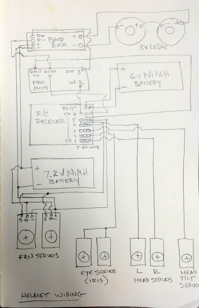
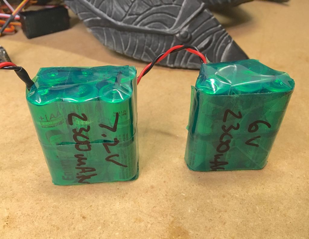
I also made two battery packs using AA NiMH cells- one 6V pack for the radio receiver, Arduino, head and eye servos and a 7.2V pack for the fan servos and eyes. The reason for this is the fan servos are rated for higher voltage and draw more current and the eye LEDs also want 7V + input power. In order to do this the fan servos are still connected to the radio receiver, but only using the signal and GND wires. The output from channel 6 on the receiver provides +6V, GND and the signal to input pin #2 on the Arduino. The output from the Arduino pin #3 provides the signal to the FemtoBuck to dim the eye LEDs. The wiring diagram shows all of the battery and servo connections and how power is routed in the system.
And with that I was able to get a full range dimmer for the eye LEDs using the RC transmitter. Here's the first test video-
Discussions
Become a Hackaday.io Member
Create an account to leave a comment. Already have an account? Log In.