 Arthur Admiraal
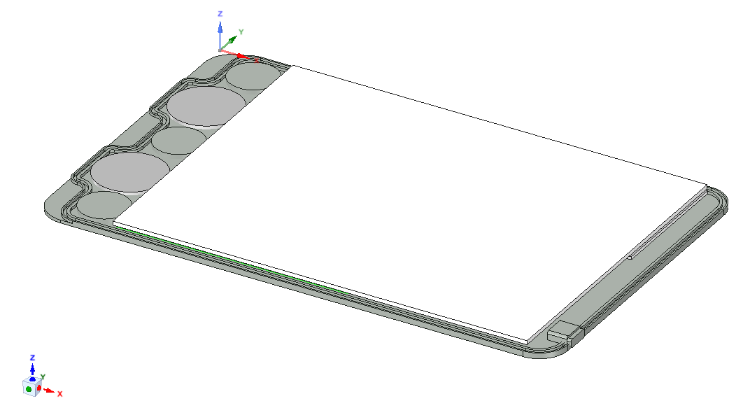
The only real mechanical part of this project is the enclosure. As mentioned before, I want to make it waterproof. Also, it needs a glass plate for the stylus localisation.
When trying to write on a device, you hand may be positioned next to it, which could put stress on you hand. To alleviate this, I want to make the device as thin as possible. This calls for a strong, solid material. Because of the small physical size, I had to make a rough case design before actually laying out the PCB to know the space constraints.
I want the design to be openable, so that it can be serviced. I came up with a host of ideas to achieve this, but only one was practical.
At first I considered making a case entirely out of glass, with one open side. Because the glass is already transparent, all functionality of the case could be put in this one part, which made it easy to waterproof it: the electronics would be shoved in, after which the whole would be potted. However, I didn’t like the idea of not being able to service the design. This is where the openability requirement was born.
After that, my mind turned to aluminium. Aluminium is strong enough for such a thin design, is easy to work with, and its high thermal conductivity makes it feel nice to the touch.
I’ve never worked with aluminium before, but I know that for an intricate enclosure, a 3D CNC router is the tool for the job, so I went on to design it with that in mind. I have fiddled around with freecad in the past, but I deemed it too unstable for this project, so I tried working with Blender, but that wasn’t really the tool for the job, so I ultimately ended up using designspark mechanical. It isn’t an open tool, but at least it’s free.
I considered milling a pocket out of a block of aluminium, and putting an O-ring on the top of the walls. The glass plate could then be placed up on that, after which a vacuum could be formed through a small hole that would then be plugged, preferable by some easily removable means (although not to easily).
Because this would be quite challenging to make, I came up with another idea. I would keep the same design for the bottom half of the case, but glue little pieces of aluminium to it, along the sides of the case. These could then be screwed to the side of the case (from the outside), to keep the glass plate in place, and the O-ring seal under pressure. These pieces would, of course, need O-ring seals around the screws as well, since else water could leak through the screw holes into the design, as the screws leave just a little gap open. This would take up a lot of space, not to mention the difficulty of assembly.
Apart from the assembly, the other big problem with these designs is the stress put on the fragile, thin glass plate. This is where the fourth and final design was born. By splitting up the aluminium enclosure in a top half and bottom half, the glass can get the much-needed support. By having a cut out for the screen in the top part of the case, the design is kept thin. Gluing the glass to the top part of the case ensures a waterproof cut out. The screen may have to be glued to the glass plate for added support. An O-ring seal can be made halfway in the walls (see picture above (note: the bottom should come down and touch the two 'teeth', but I am not done designing the enclosure yet)). If the screws are placed only around the perimeter, the O-ring can loop around them, so water wont leak in via the screw holes. To prevent the aluminium from rusting, the parts can be anodized.
There are some potential problems with this design though. The speed of sound in anodized aluminium could be higher than that in tempered glass. Because of this, the aluminium could absorb part of the signal, and get it to the ultrasound microphones quicker then the glass could, which would mess up the calculations. Also, if the bond between the glass plate and the aluminium top part of the case is too strong, the aluminium could end up absorbing too much of the signal for the glass to be able to pass it through to the ultrasound microphones. I’m hoping that the plasticity of the glue will allow the glass to vibrate freely, and thus pass the wave on with a relatively low loss, in which case both of these problems should be non-existent.
Cosmetics
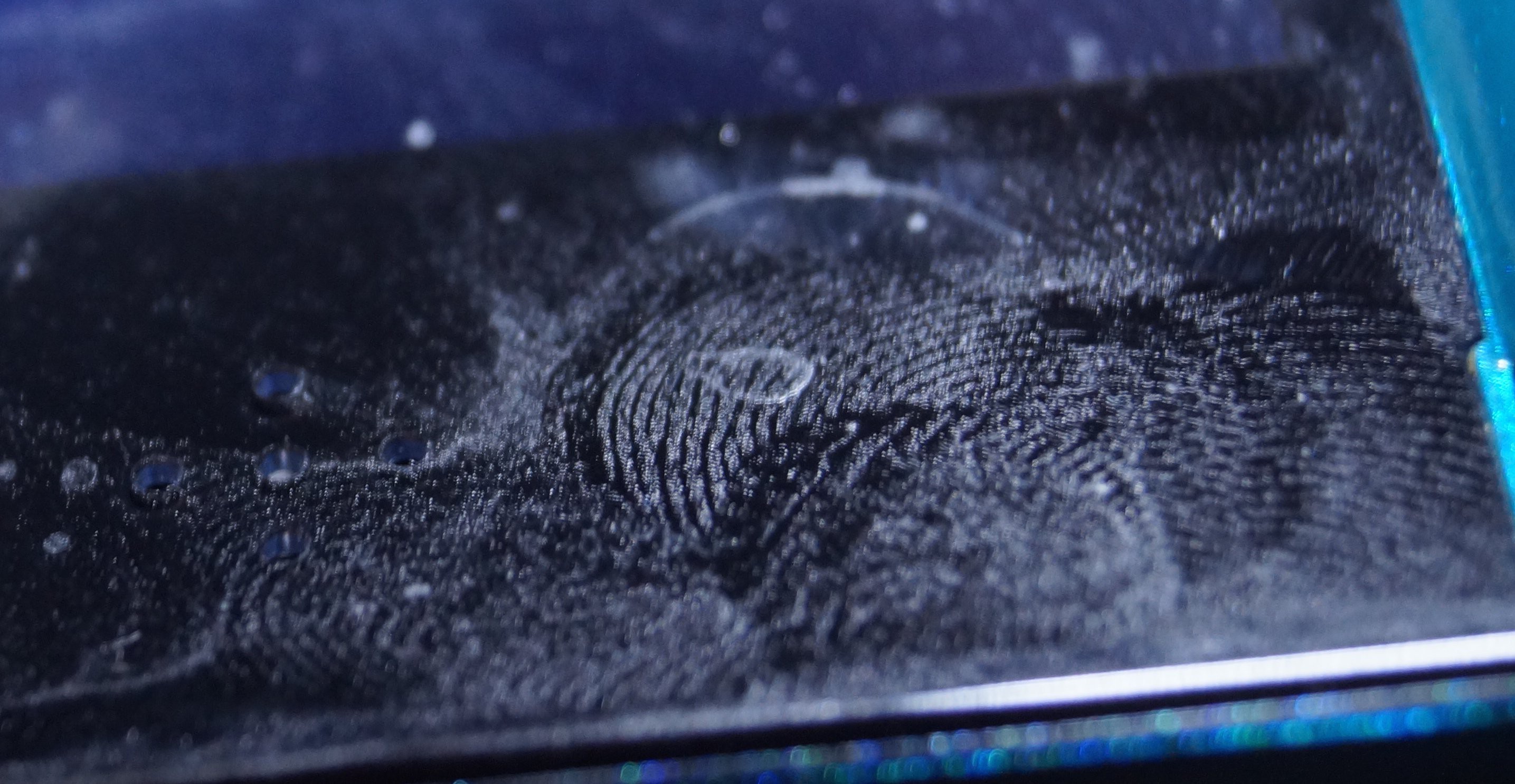
There is one thing in product design that I just hate to no end. So much in fact, that I’ve decided to never do this in my own designs: glossy surfaces. You can easily see every fingerprint on a glossy surface, while diffuse surfaces keep looking just as good as when they came straight out of the package. Anodized aluminium keeps the same surface finish as the aluminium underneath. Normally, this would be polished, so that the anodized surface would be my arch nemesis: a glossy surface. To create a nice diffuse surface, the part can be sandblasted prior to anodizing. Sand is too rough for this however, so glass beads are used, and then the process is called peening. But glass beads can get stuck in the aluminium, which can be decrease the quality of the anodising. According to this CNC machinist forum, aluminium oxide yields the best results. I’ll try if I can peen my part with that, but I’m afraid that I will have to resort to regular glass beads.
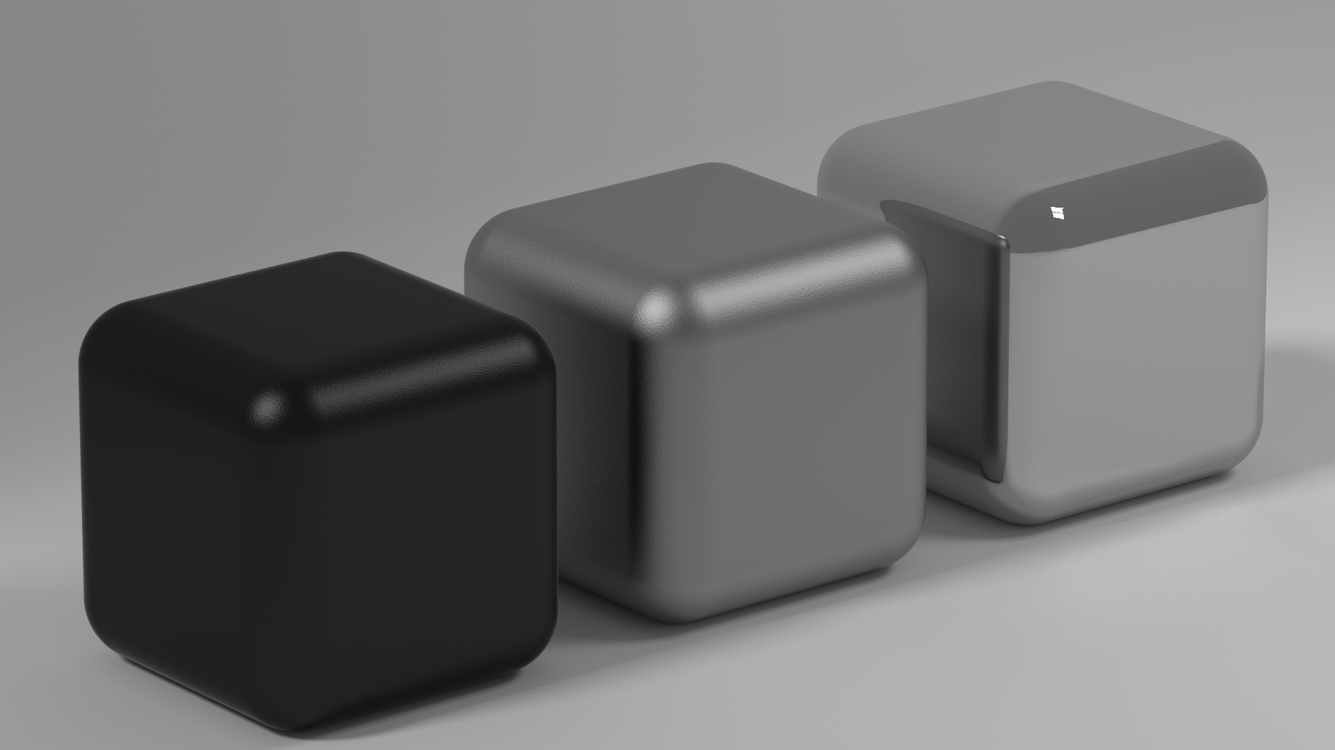
Anodizing actually allows you to color or dye the surface. I’d like to color it black for some reason. On the picture below you can see a mockup of what I think the aluminium might look like. On the right it is straight from the polishing, in de middle it has been peened, and on the left, it has been anodized.
Well, that were all the general design decisions, in the next posts I'm going to dive into the details of the hardware design.
Discussions
Become a Hackaday.io Member
Create an account to leave a comment. Already have an account? Log In.