 Arthur Admiraal
Now for the tricky part: accurately measuring the delay between the incoming ultrasound signals on the microphones. First, I amplify the signal using some cascaded negative feedback opamp circuits.
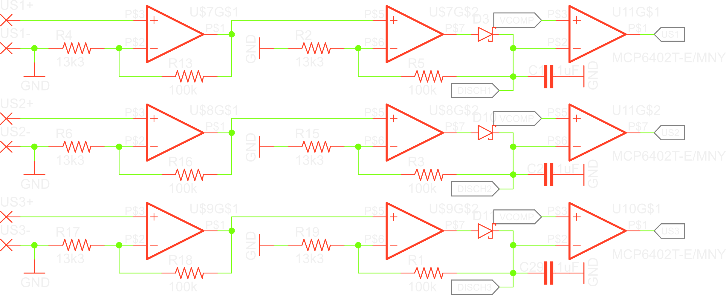
There is actually only so much gain you can get of an op-amp at a given frequency. The gain-bandwidth product has to remain constant. To get around this, you can cascade them. That is what I did here, to increase the overall amplification.
I’m only interested in the presence of the signal. Amplifying the negative peaks of the signal would be a duplicate of amplifying the positive peeks, just in the other direction. I don’t bother with that, and just clip those. To accomplish this, I have ground as the reference level of my amplifier. Everything above that will become higher, everything below will become lower. The negative-going peaks will become more negative, but since the output of the amplifier can’t go below the negative supply voltage, which is ground in our case, the output will just stay at ground.
The second amplifier is then hooked into a peak detector circuit.
When the amplifier detects the ultrasound signal, it steers its output pin to V+. This signal then charges a capacitor through a diode. When the signal dips down to GND again, the capacitor can’t discharge because of the diode. I get to why this continuous high signal is important in a bit.
I’ve connected the feedback pin of the second opamp beyond the diode, to mitigate the forward voltage of the diode. It will try to compensate for the voltage drop in the diode, ensuring that the signal is always amplified correctly.
I then pass the signal to a comparator. It has a lower threshold than the microcontroller, so it will detect the signal more easily. This reduces the need for amplification.
After all the delays have been measured, the capacitors can be discharged for the next cycle. I’ve hooked each up to a pin of the microcontroller. I didn’t want to connect them together using diodes, in case the leakage current would be so high that one capacitor could charge up the others. The microcontroller pins can stay in a high impedance state, until it is time to discharge the capacitors. Here comes a flaw in my design: I didn’t think to put resistors between the capacitors and the pins. Because of this, if I’m not careful when programming, I can short out power lines, if the output of the opamp happens to be at V+ when I pull the microcontroller pin low. To avoid this I have to only have the pins in either a high impedance state or switched to the internal pull-down resistors.
Measuring the delays
I wanted to have a decent resolution on the position of the stylus. I drew some letters, as small as I could, and measured the height of them. They were about 2mm tall. I figured that 16 data points in the height would be enough, so that gives a resolution of 0,125mm. I read here that the speed of sound in glass is about 4000 m/s, but since I will be using tempered glass, which is harder, I can only expect the real speed to lie a bit above that, so I scaled it up to about 5000 m/s. To calculate the time we want to discern, we just have to divide these:
Wow. That’s very little. And let’s also calculate the maximum value we need to register, assuming the maximum distance is about 20cm:
The number of bits needed to store the range of values then is:
At first I wanted to use some counter logic IC’s, attached to a fixed clock. The first pulse would enable them, and the second disable them. The amount of pulses could then be read in from their outputs., probably using shift registers. Of course, the chips had to be special high-frequency logic chips, such as the Fairchild 74VHC4040MTCX. This could’ve worked, but I’m not really comfortable with such frequencies yet.
So I set out to look for some kind of stopwatch IC, that would start counting on one pulse, and stop on the next, and have some nice digital read-out. I eventually found a datasheet for the Texas instruments TPL7200. Which does exactly what I want. It has even higher resolution than I need. However, this chip doesn’t exist. Instead TI has marketed it as the TDC7200. There is only one disadvantage: the price. The power consumption may also seem high at 1,35mA, but this is only in measurement mode, which will only happen periodically in short bursts.
I’ve three microphones. The signal will always arrive at one of them first, and then another and then another. I only need to measure two delays, but they are always between different microphones. I only need two of these expensive chips each measurement cycle, but to capture the delays in all cases, I need three. Or do I?
I’ve devised a way to route the signal two only two TDC7200s, depending on which microphone first picks up a signal.
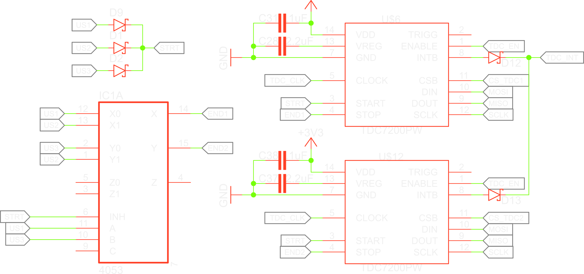
First, one microphone detects a signal. This is coupled to the start pulse of both pins. It doesn’t matter on which one the signal arrives, as they have all been connected using a diode or-gate.
Now it is determined which signal goes to which IC. For this I use a 4053D multiplexer IC. This chip basically contains 3 digital relays. It contains 3 modules in which you can select which of two pins you connect to a pin. I only use two of them.
I have one input of both modules connected to the middle microphone, and the other pins connected to the top and bottom microphone, for each module respectively. The signals determining the routing have also been connected to the top and bottom microphone. The standard position of the modules is on the top and bottom microphone.
This way, when a signal comes in on the middle microphone, it sends the start signal, but the other microphone signals are routed to the stop signals. When one of the outer microphones is the first to receive the signal, it will send the start signal, and route the middle pin to its end signal.
It is for this switching that the peak detection circuits were necessary, so that the routes wouldn’t be temporary.
I’ve hooked some interrupt pins of the microcontroller up to the microphone signal so I know which one received the signal the first, and how the delays were measured.
When the signals of the outer microphones hit first and do their switcheroo, they can still pass through, but they will hit the TDC7200 when it isn’t ready to except the stop signal yet. However, if they aren’t the first the signal should register.
So those were all the details on the electronics design. Next time I’ll write about the PCB layout.
Discussions
Become a Hackaday.io Member
Create an account to leave a comment. Already have an account? Log In.