 Arthur Admiraal
Before continuing the logs, I thought it might be a good idea to actually fulfill the requirements of the competition.
Introductory video
Script
Hello world!
My name is Arthur Admiraal and I am a 16-year-old electronics hobbyist from the Netherlands.
In this video I’m going to tell you a bit about my entry to the Hackaday prize: the Squidpad.
Ever tried to draw something on a computer? When I did, the user experience was cumbersome at best. On most devices, you can’t lay down your hand on the device as you do with paper, the accuracy is terrible and booting up just takes far too long.
For that reason, I find myself falling back to paper whenever I need to make a quick sketch to organize my thoughts, do some quick math or draw a schematic.
Paper is messy though. Serious effort is needed to organize it, and it isn’t natively searchable. Also, it doesn’t have the same advanced functions that digital media has. Ever tried to resize something on paper? Not easy, I can tell you that.
There are of course devices that make drawing on a computer easier, but they are either really expensive, lack a screen, are not mobile, or don’t fully fulfill my requirements.
In my opinion, a device is needed that is specifically designed to replace sticky notes and scraps of paper scattered around the average household. It should have the same ease-of-use as paper, but add the advanced functionality of digital media to it, such as searchability and semi-automatic drawing tools.
I’ve spent the last few weeks designing such a device and I have dubbed it the Squidpad. It will feature a 6” e-ink display, a CNC-routed 5.2mm thin aluminium enclosure, accurate localisation of the stylus using ultrasound signal trilateration, a USB compatible interface to download your drawings saved on the internal micro-SD card to your computer and between 20 and 200 hours of battery life depending on how good I am at low power design. I have ideas for other, more advanced features, but I want to get these basics working first.
As of creating this video, the electronics design is done, and I’ve been documenting it while waiting for the parts to come in. Because of this, I haven’t been able to build a prototype and test anything yet.
Apart from documentation, I’m currently working on designing the enclosure.
I have made all files available on GitHub under a CC-BY-NC-SA license.
Well, I hoped you liked that quick introduction to the Squidpad, feel free to check out the logs in which I describe the project in more detail, as there is only so much that you can explain in a two-minute video.
System design document
Here is a high-level block diagram of the device:
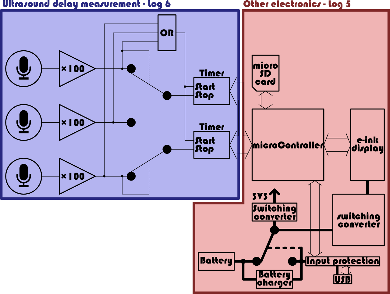
I've described how the ultrasound delay measurement works in log 6. I still have to explain the basic operation of the other electronics. So, without further ado, here is a high-level explanation of the typical operation.
The stylus sends out an ultrasound pulse. As I haven't designed any part of the stylus yet, I haven't included it in this diagram. During testing I will just be using an ultrasound transducer hooked up to a signal generator. The ultrasound pulse reaches the microphones. The delays between the pulses hitting the microphones are measured via the procedure described in log 6. The micrcontroller now reads out these these delays, and calculates the position of the stylus with them, as described in log 2. It then calculates the pixel which need to be marked to form a line between a current position and the last position. These, and only these pixels are marked on the e-ink display. By forgoing a full update, the power consumption is lowered and any problems with the low refresh rate are mitigated. These pixels are also marked on a bitmap file stored on the micro-SD card which also serves as a frame buffer, in case anything needs to be erased. The microcontrollers RAM would be too small for such a full frame buffer. The micro-SD card is connected to a separate SPI-bus so that a SPI signal to other chips won't prevent it from entering sleep mode. I wasn't sure if this would be a problem, but I prefer not to take chances.
A new line can also be drawn in a SVG-file on the micro-SD card. A few past coordinates could be stored in RAM so that the curves could be optimized somewhat on the fly.
Between pulses, all devices enter sleep mode for reducing power consumption. The input signal from the microphones interrupts both the microcontroller and timer ICs, so that the pulse can be registered and the microcontroller can activate other important devices.
When connected to the computer via USB, the device switches to USB power, and initiates charging. This is described in log 5. The microcontroller can then appear as a mass storage device, and the files can be copied to the hard disk of the user's computer. The device has some input protection on the USB as described in log 5.
Whether the device is switched to its internal battery or external USB power, the 3.3V switching converter will generate a voltage for most ICs to use, except for the switching converter powering the e-ink display, which also uses the raw input voltage for increased efficiency. This one is only activated when the e-ink screen needs updating however.
As mentioned before, currently all electronics is designed, but not yet built en tested.
The regularly scheduled logs will resume tomorrow.
Discussions
Become a Hackaday.io Member
Create an account to leave a comment. Already have an account? Log In.