 Arthur Admiraal
Look what just arrived last Saturday:
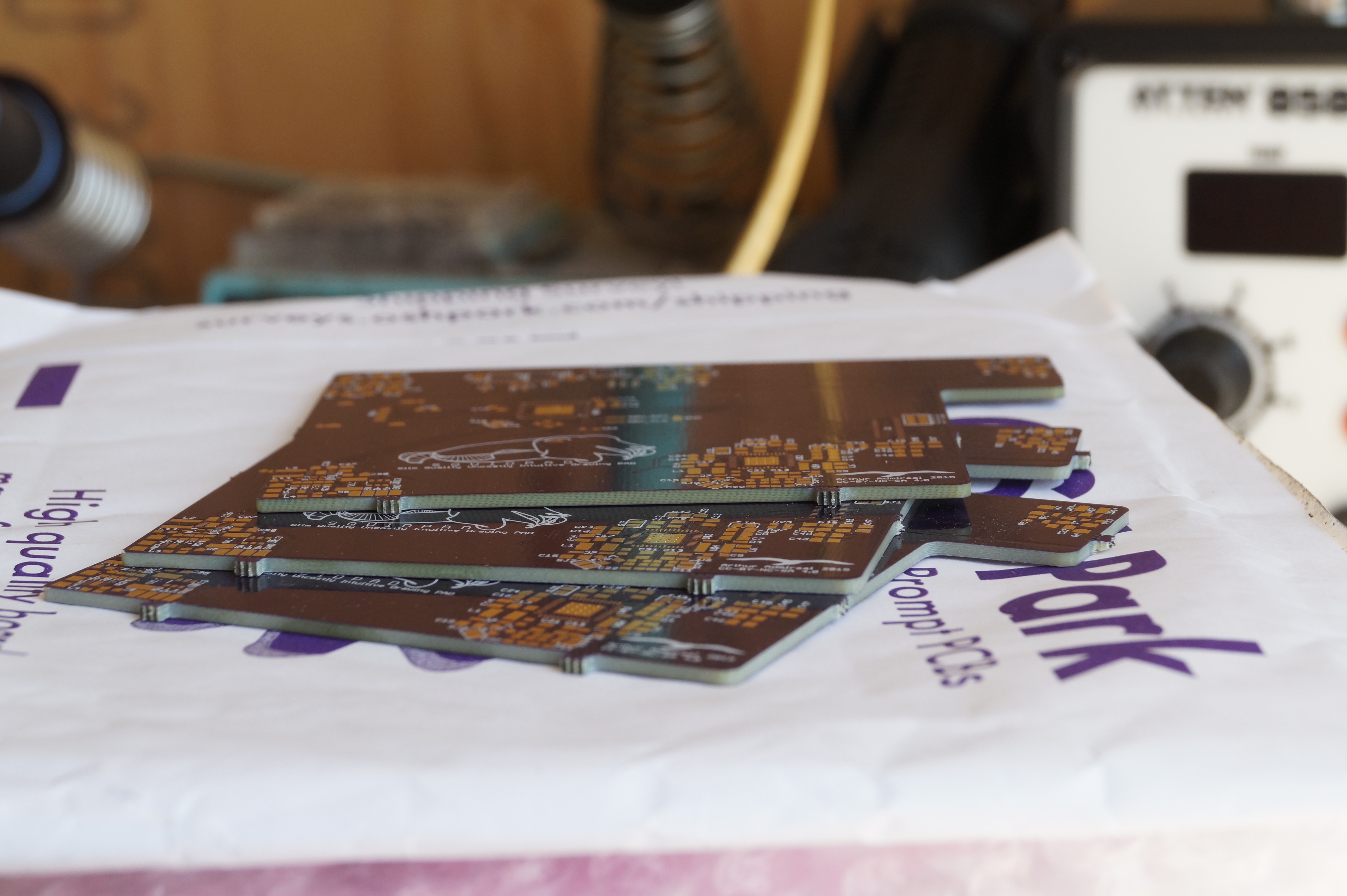
That’s right: the final parts arrived, being the PCBs. I of course went to work immediately on soldering the prototype together. This was my first stencilled design, so there were some irregulaties during soldering, but after re-reflowing most of them could be resolved.
 I only had real trouble with soldering the connector for the e-ink display. In fact, I broke it in the progress. Luckily, I ordered two just in case. I have decided to wait with soldering this part until I have the microcontroller actually up and running, just to prevent my self from going insane because of one annoying connector.
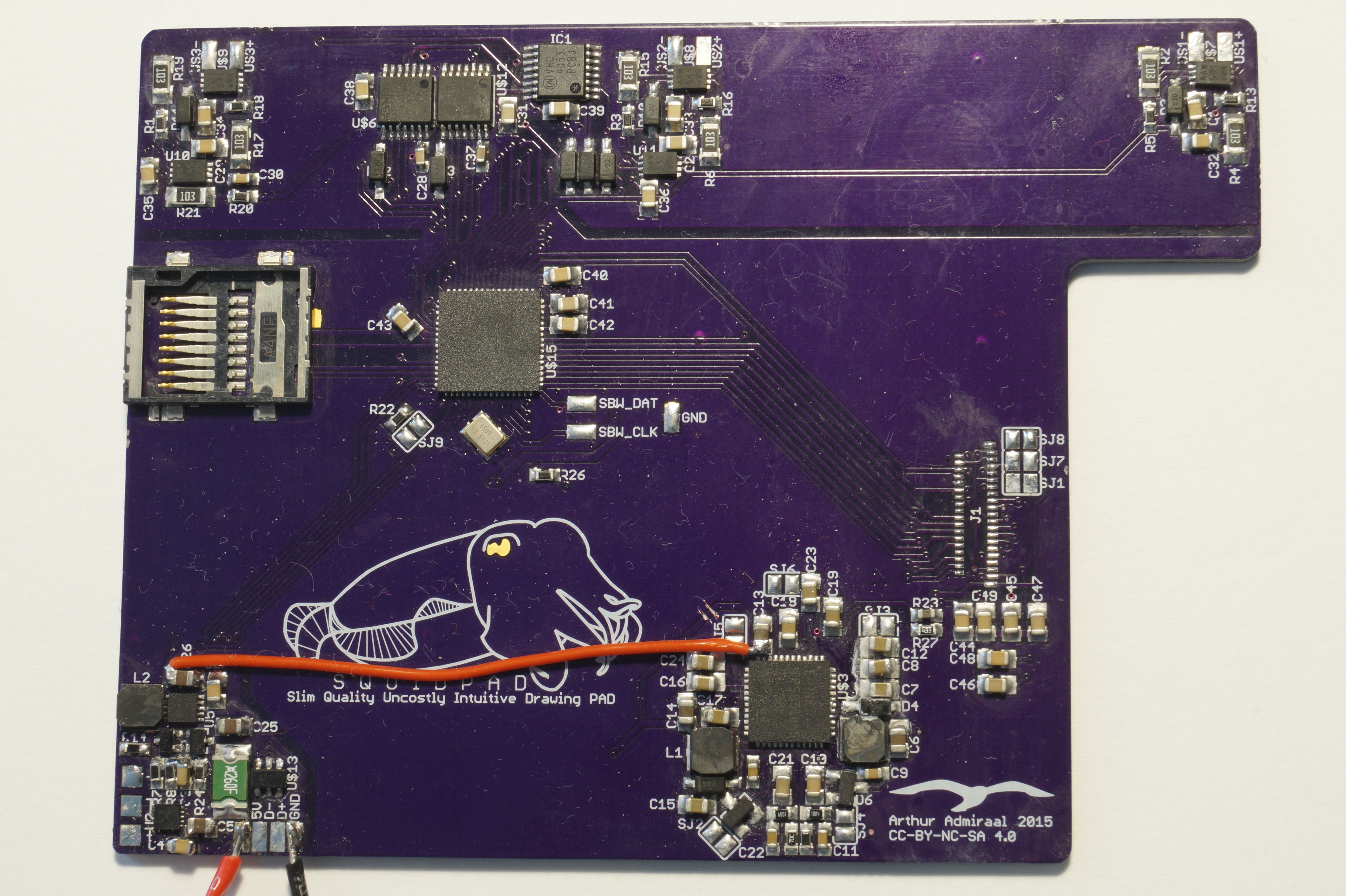
In the end I got the following result:
Errata
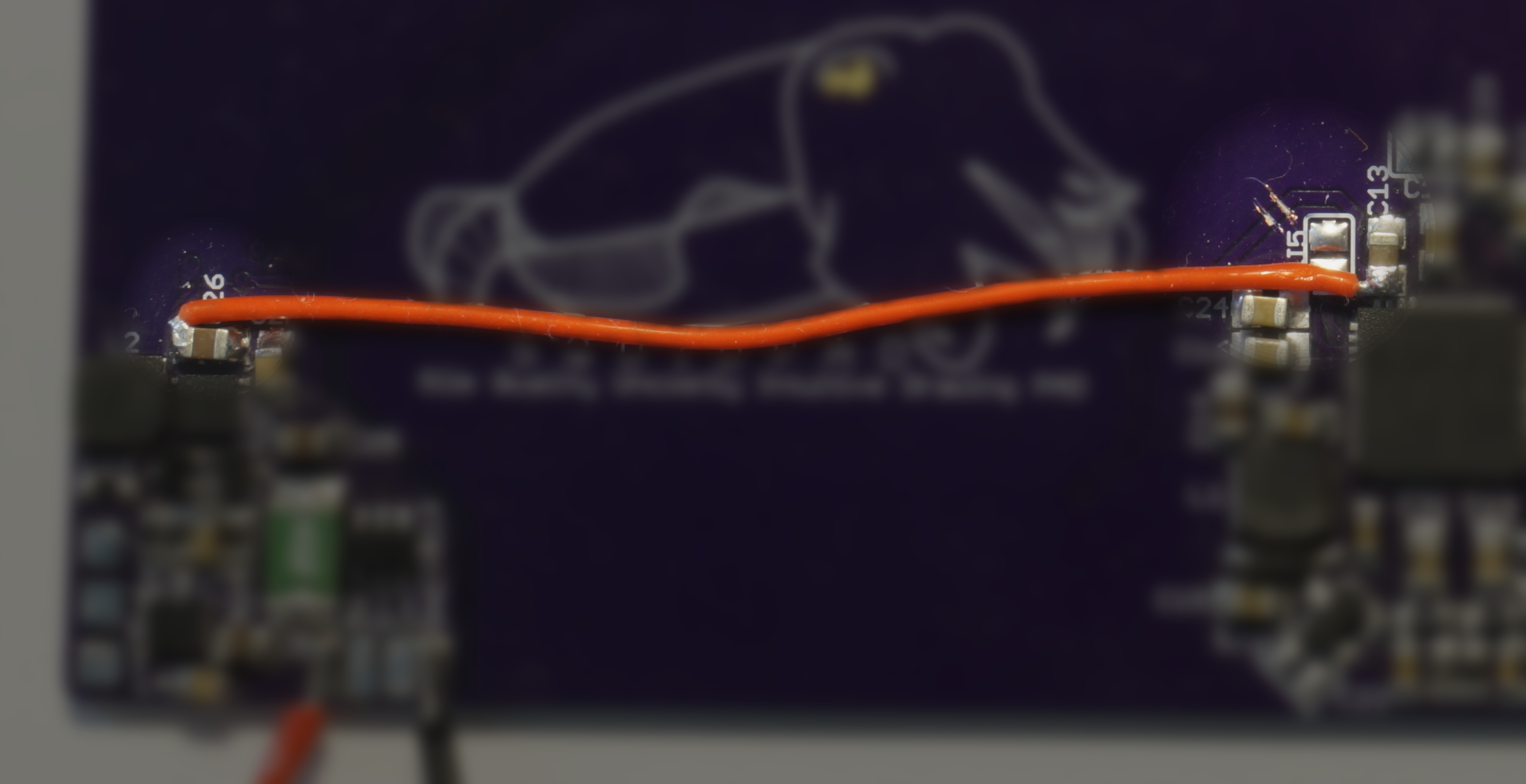
I found that the io-voltage of the e-ink power chip was hooked up to the raw input voltage of the system, and not the regulated 3.3V. As a consequence, the microcontroller could receive a relatively high voltage on its input pins, which could blow it up. Because of this, I cut the trace leading to it (in two spots for good measure) and soldered a bodge wire from the 3.3V output capacitor to the input capacitor of the chip.
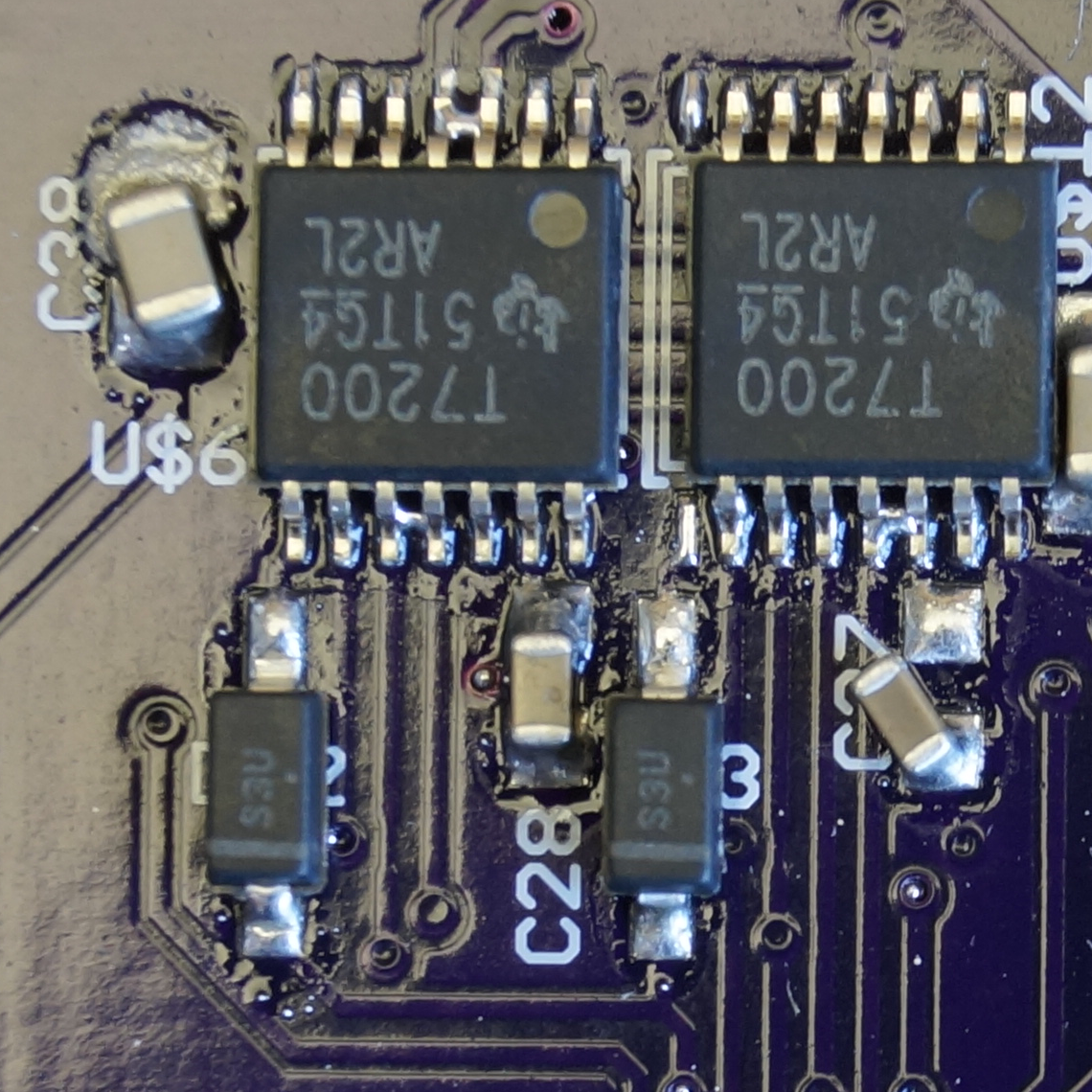
Also, some passives had a too small or too large footprint, or were to
close together. Furthermore, some chips had too much solder paste on
them. These faults in the PCB design were propably the main cause of the need to re-reflow a lot of stuff, having to sometimes
wick up extra solder.
Powering it up
I have done a quick power-up test, feeding in an about 10mA current-limited 5 volt into the USB bus, and I measured the 3.3V line to be a nice 3.4V at no load. Even after increasing the current-limit to 1A, the magic smoke didn’t escape.
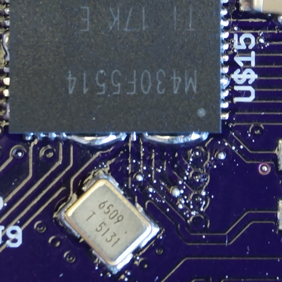
My next step is to see if I can program the board via the USB boot loader that is programmed into the MSP430F5514 by default from the factory. I haven’t had time to do this yet as school has begun again here. Being in my final year, I also need my time for some school-related research projects. This is also the reason this post is so late. I think that I can spend some time in the weekends on this project though, so expect some updates in the weekends.
Hopefully I will be able to tell you all about programming a MSP430F5514 via the USB boot loader next time.
Discussions
Become a Hackaday.io Member
Create an account to leave a comment. Already have an account? Log In.