Close
0%
0%

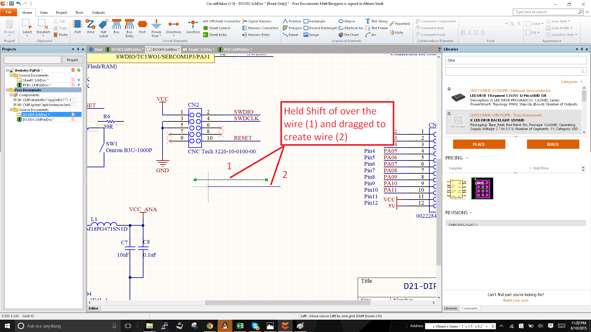
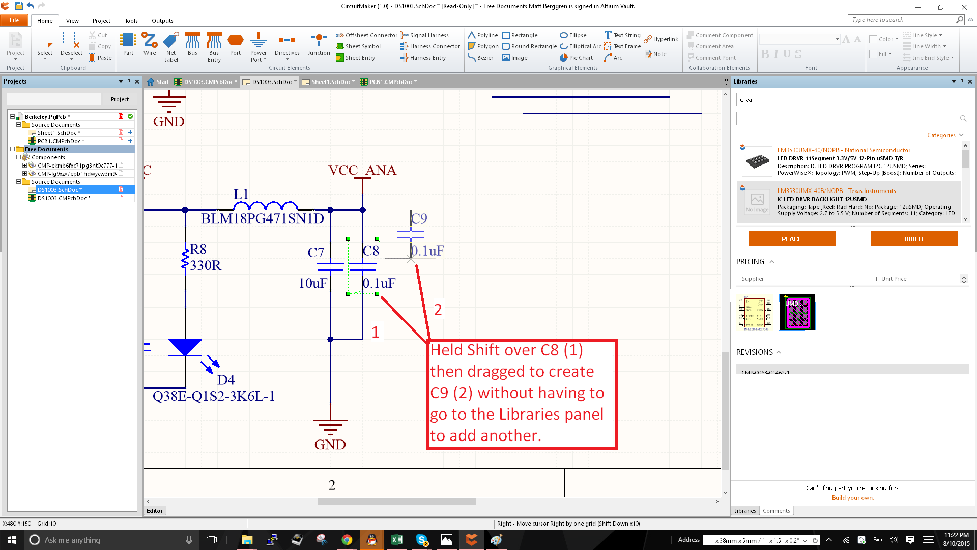
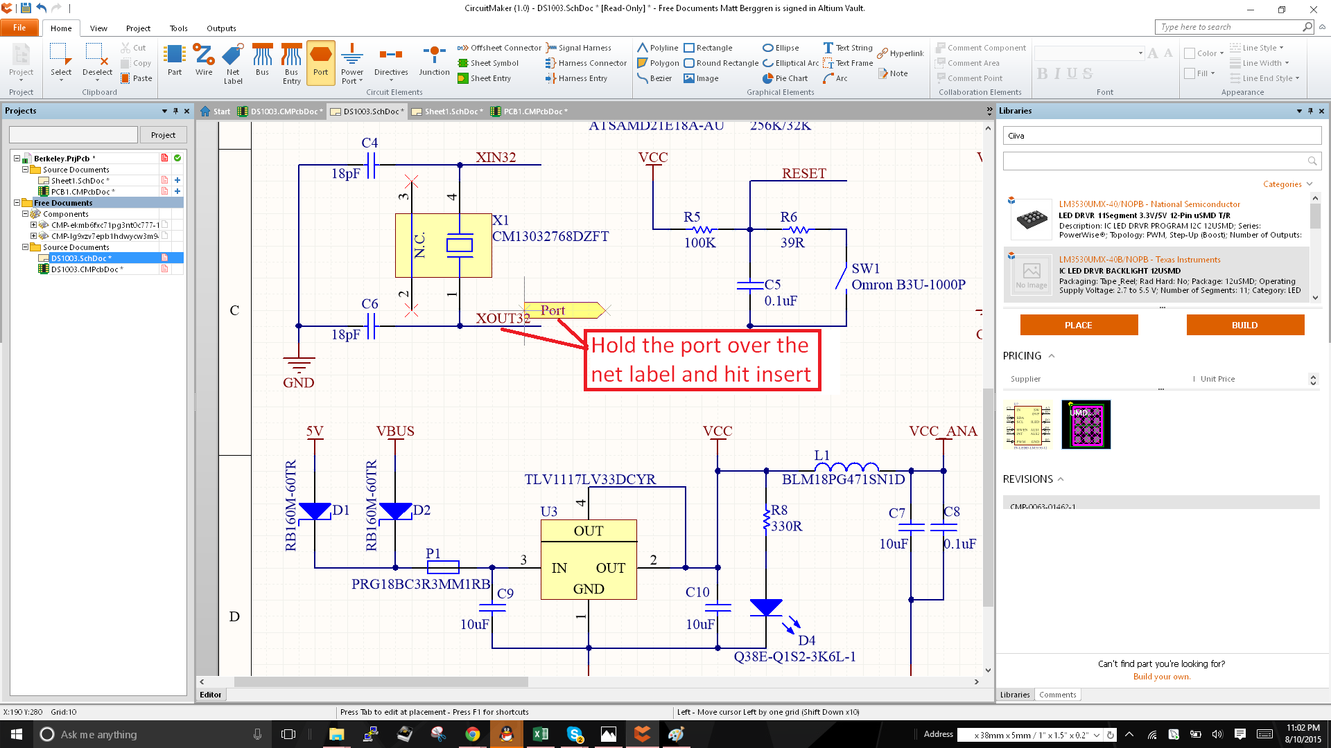
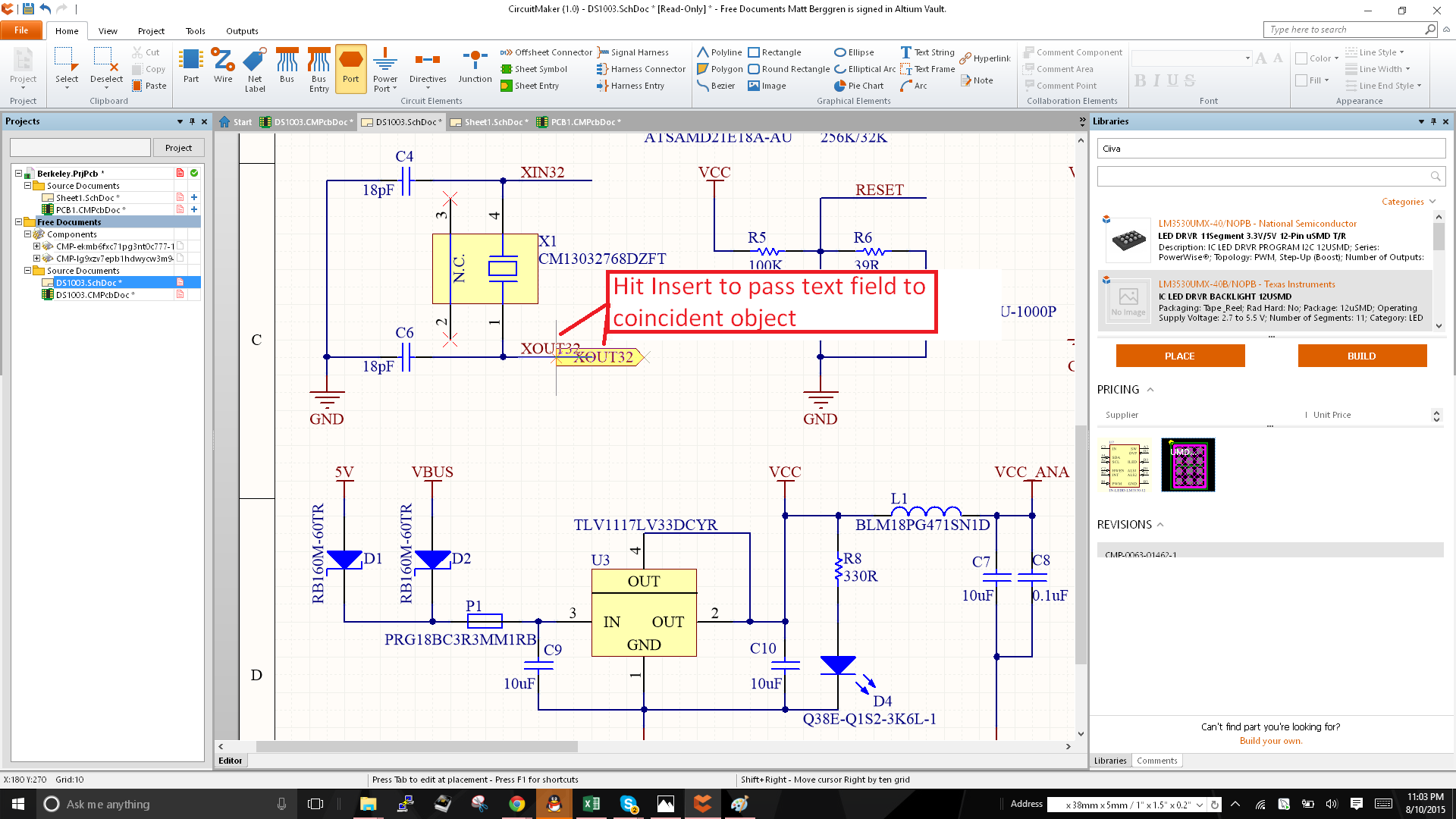
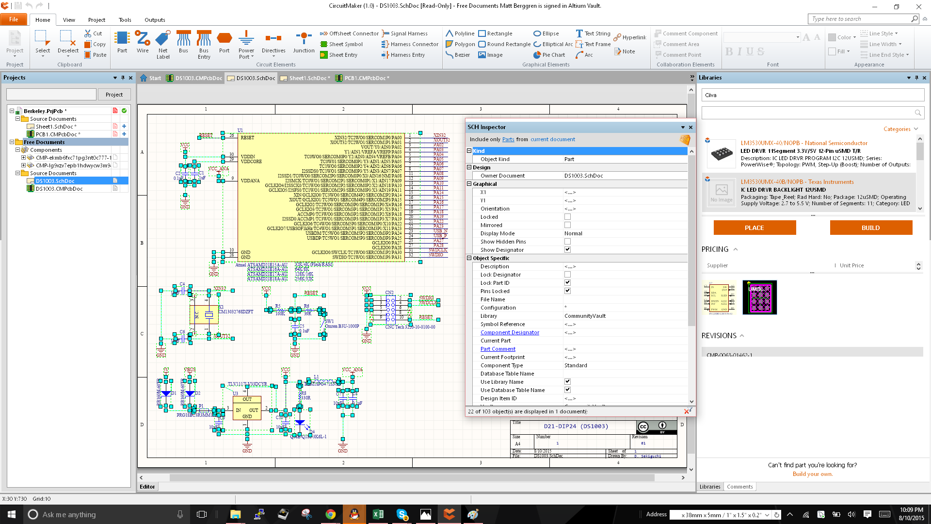
Tips for Using Circuitmaker

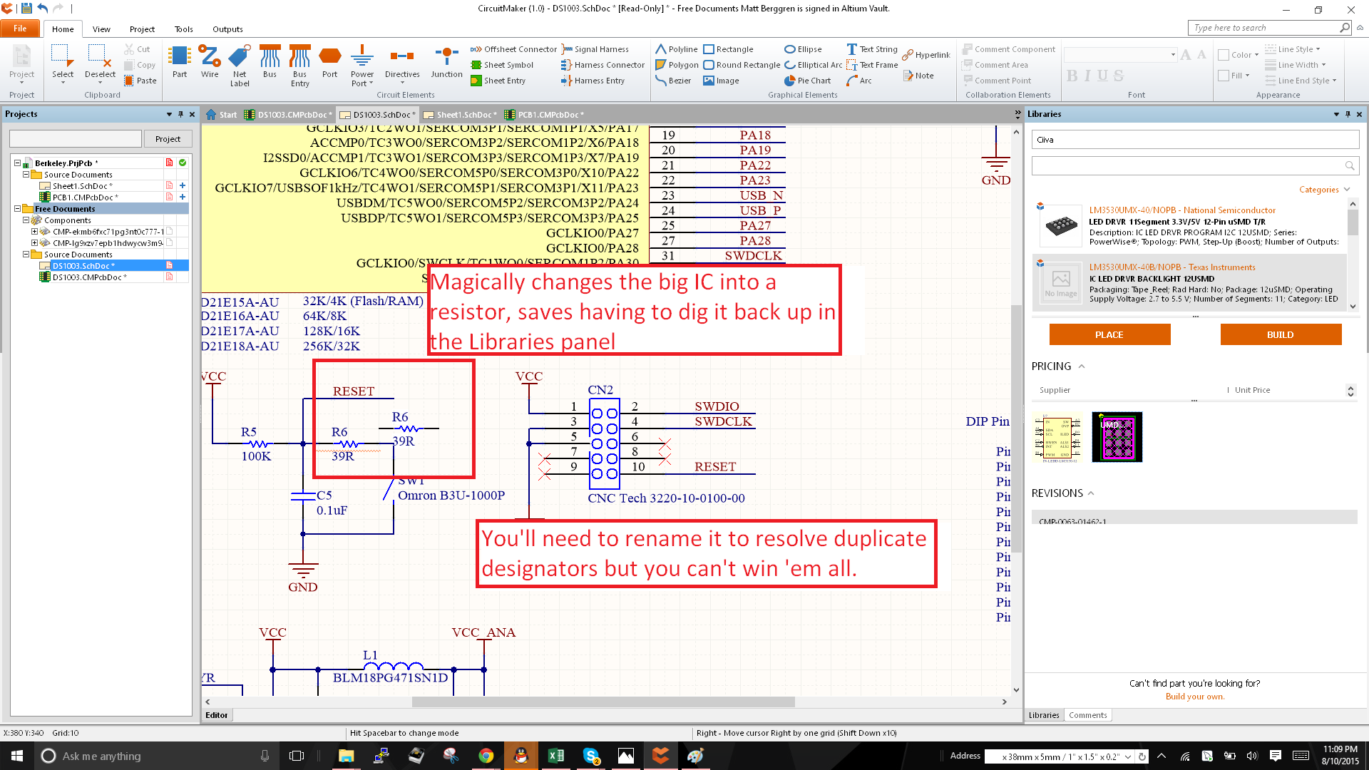
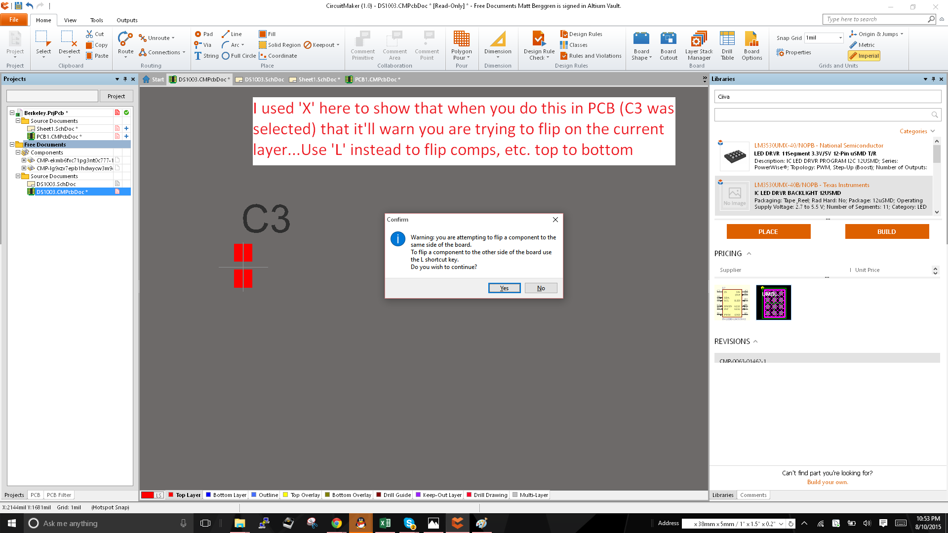
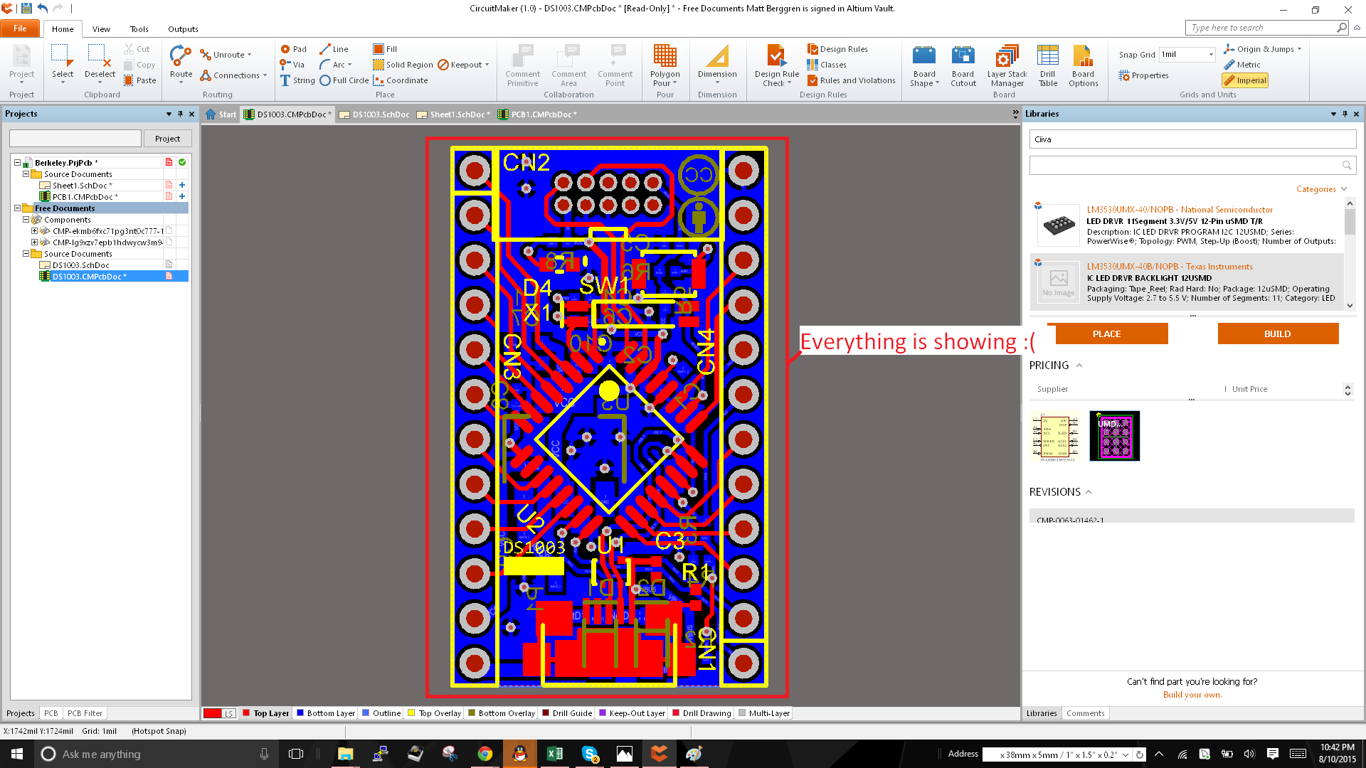
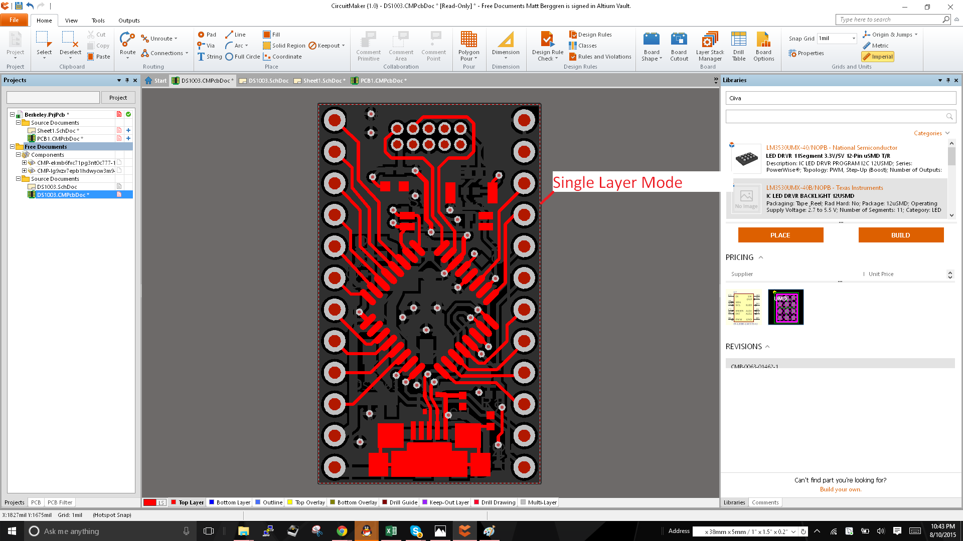
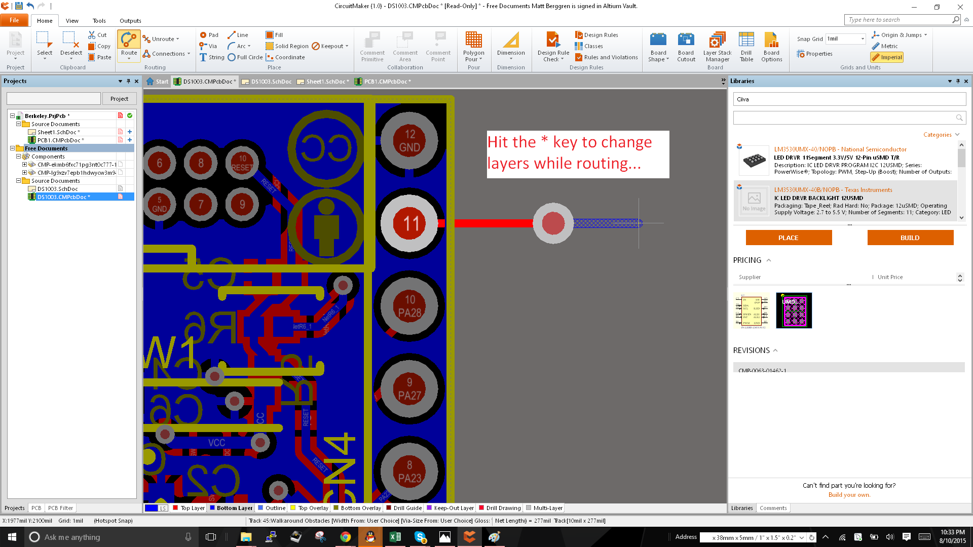
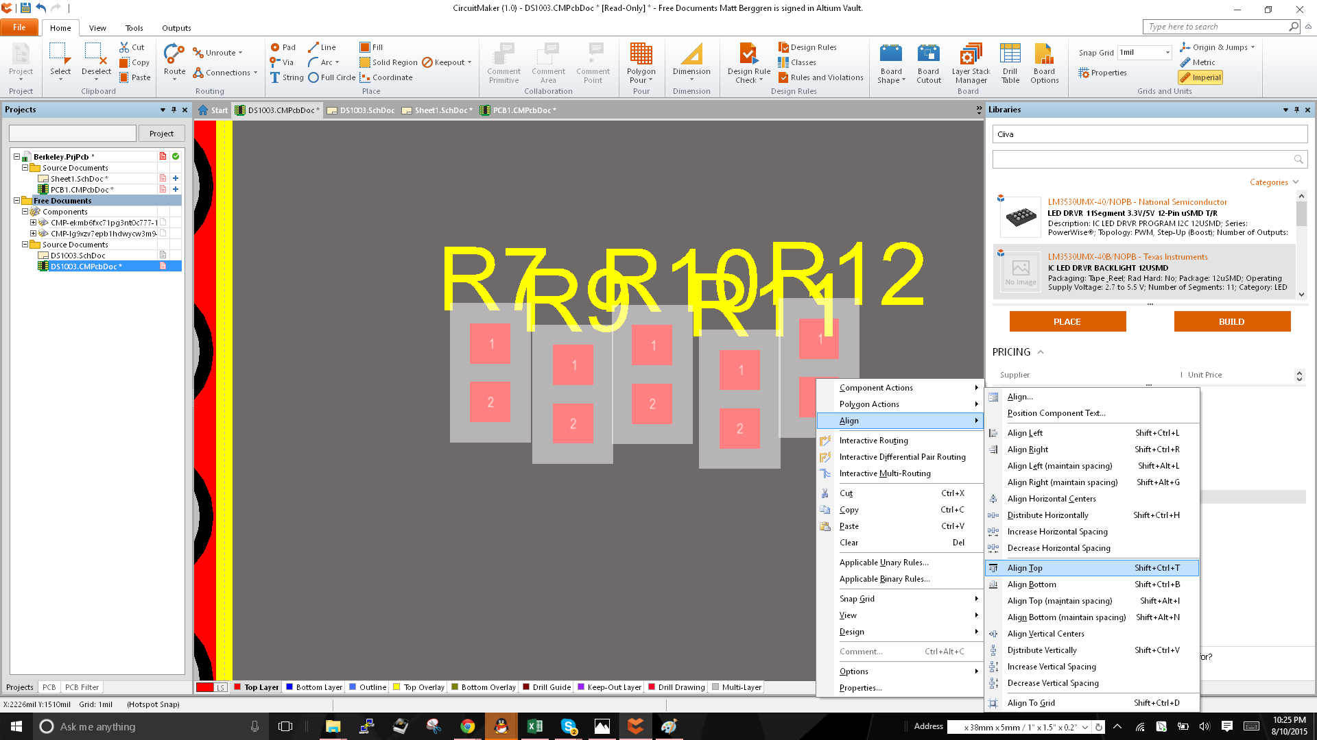
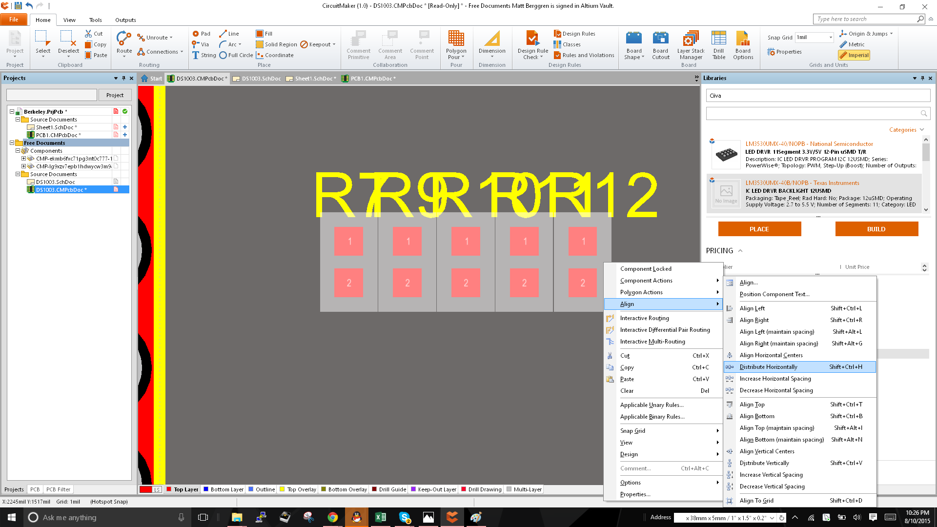
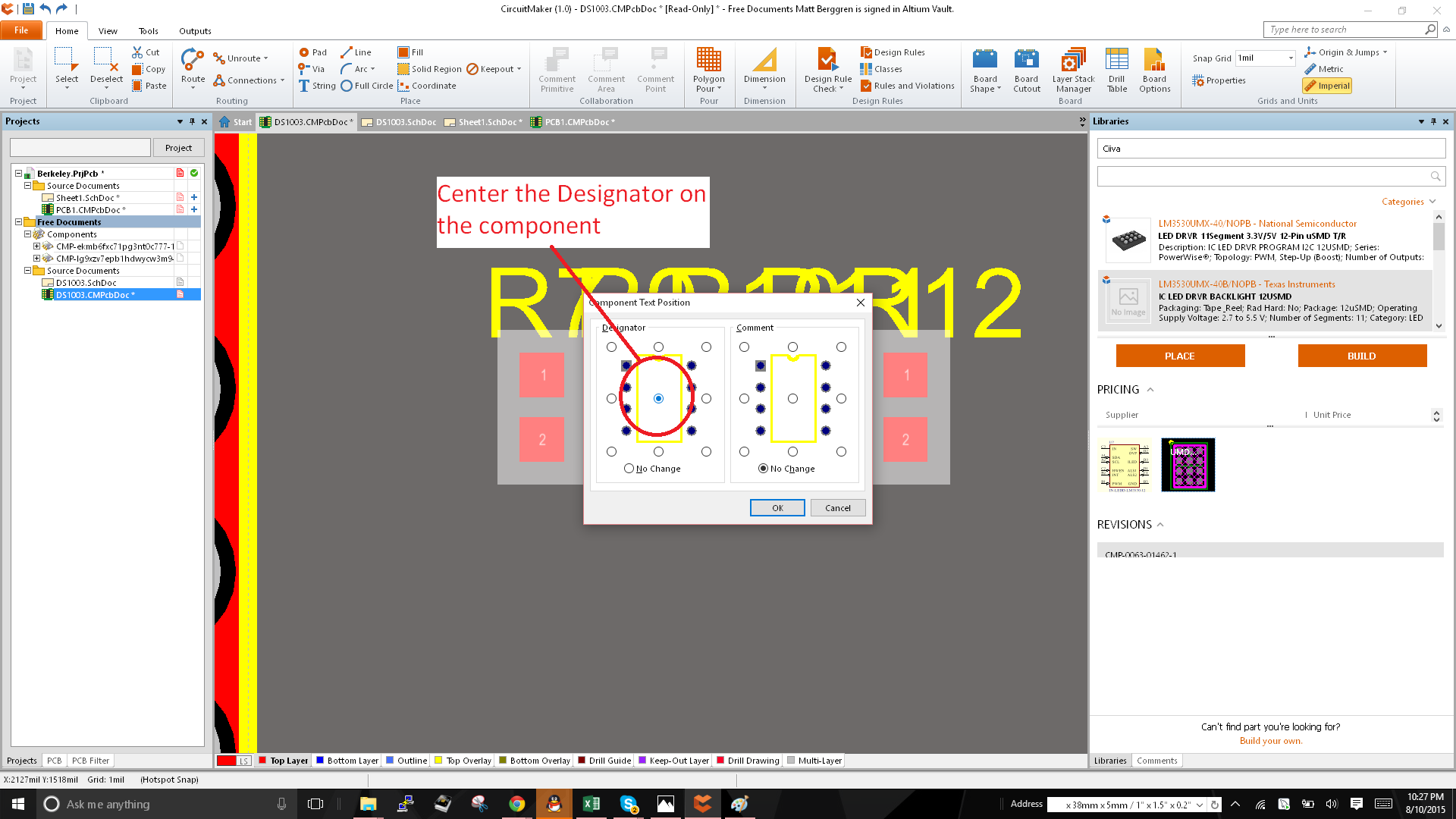
This is a list of tips and tricks for driving Altium's Circuitmaker software like a pro

Similar projects worth following
NOTE: Read the project logs (expand them). Some material is for total newcomers, other materials is for everyone using Altium or basically any version.

Full disclosure, I spent many many years of my professional life supporting, building and implementing design tools for Altium or an Altium acquisition, PCAD, prior to that. This project includes a few gems that are both available in the free version & that everyone should absolutely know. They also work in Altium Designer so for anyone with an Altium license, be sure and have a look to see if there's anything you didn't know about. No particular order, just a nice list of interesting things that make CM much easier to use. The images are from someone's public project in the Circuimakerverse.

See the full list of project logs (you have to expand them) to see all of the tips I'm lazily adding at my pathetic leisure.

  • Shift + Drag duplicates object beneath the cursor

    technolomaniac08/11/2015 at 06:25 0 comments

    So you have placed a wire in schematic that is exactly 100 units wide. You're proud of yourself because this is exactly what you wanted and you did it! Woohoo! If you want another, simply hold Shift and drag on top of the wire and it'll duplicate it. Now you decide that you really wanted 4 wires. Select the first two (draw a bounding box or use Shift + Select to multi-select the wires) and hold Shift and Drag. Voila, two more, perfect 100 unit long wires. Lather, rinse, repeat.

    This also works for components. So take a case where you would otherwise have to go back to the Libraries panel and find that totally common 0.1uF 0603 cap you're already using in 5 different places in schematic. Blaggh. Noob. Instead, find and existing one and click it. Then follow it up with the mighty Shift + Drag to duplicate it. It'll increment the designator for you (you'll be on the hook to make sure you don't end up with duplicate designators).

    Can't emphasize this enough...This is a massive time saver!

  • 'Insert' key copies properties from coincident objects

    technolomaniac08/11/2015 at 06:13 0 comments

    Ok...this one is truly pro's only. If you have a net label in schematic and you've name it Foo as seen in the example, and then you want to create a port with the same name...you can either edit the port and type "Foo" like the noobs do, or you can hold the port over the net label, hit "Insert" and the name of the coincident net label will be transferred to the port without you having to (mis)type it. A much easier way to duplicate the text in one thing, and transfer it into another. If you do this with components, it'll pick up the component under the cursor and the component you have hanging off your cursor will become a duplicate of the one beneath it.

    Hit insert when they overlap to copy text field between object types...

    --

    Place a new part and hold over an existing component...

    Hit the insert Key to convert to component under the cursor...Saves having to open the Libraries panel and finding parts again...Blaggh!

  • X/Y Flips in Schematic, L flips comps in PCB

    technolomaniac08/11/2015 at 05:56 0 comments

    So in schematic, if you want to mirror something, you can use the X/Y keys. That'll mirror in the respective directions without having to edit the object properties. Just select and hold and object (or when it's hanging off the cursor during placement mode) and use X/Y to flip. Careful in PCB...when you want to flip in PCB, you can use X/Y for non-component objects but if you want to flip layers from Top to Bottom for components, use the 'L' key while the component is hanging off the cursor (or just click and hold to select it). If you try the X/Y on PCB with components, it'll warn you that you're flipping on the same layer. This = bad.

  • Shift + S toggles single layer mode in PCB

    technolomaniac08/11/2015 at 05:47 0 comments

    Sometimes what's on PCB is just too confusing and there's benefit to seeing only the stuff on the layer you're routing on. If you press Shift + S you'll cycle in/out of Single Layer Mode; a mode in which only the currently selected layer is visible and all other objects are masked. When you change layers in this mode, it'll follow you to the subsequent layer. Nice for tidying up text on the PCB too! If you want to control what layers are being displayed, use the 'L' shortcut to launch the Board Layers and Colors dialog and enable/disable layers. See images below.

  • Backspace rolls back track & wire segments

    technolomaniac08/11/2015 at 05:39 0 comments

    While routing there is inevitably the moment where you say "crikey...I can't go that way". Alas, there is a solution that doesn't require you to stop and delete a bunch of stuff one at a time (you could but I'd ship more products than you if you did :). Instead, just hit Backspace and it'll go back to the last point in which you clicked (the last anchor point for the track / wire). You can do this all the way to the start of the active route. If you need to later break wires, have a look at my tip on breaking wires without deleting the whole thing.

  • * key on the numpad changes signal layers

    technolomaniac08/11/2015 at 05:36 0 comments

    When routing you want to add vias and the way to do this is using the '*' key on the numpad. That'll drop a via and cycle thru *signal* (routing and plane) layers. The +/- keys will cycle all layers. Live it, love it. Sans a numpad, hit the tilde key '~' and select the command Next Layer Num * from the menu. It'll achieve the same thing without a numpad. But you should really get a numpad. You can thank me in the comments.

  • "Align" context menu makes boards pretty

    technolomaniac08/11/2015 at 05:30 0 comments

    Ok...try this. Grab a group of components. I don't care how you do it, but the easiest way is to use Shift + select to select multiple components. Now, when they all look selected, like the row of messy comps seen below, go ahead and right click on any one of them and you'll find Align in the right mouse menu. Under Align you'll have commands like Align Top, Align Bottom, etc. This'll get them into position without having to count grid points. (Do this if you wish, but I'll ship things twice as fast as you :)

    For placement, you can also use the command, Position Component Text from that same menu and center all of the component text above the parts. That'll ensure you know what text goes with what component. You can move it later to make it all pretty and such, but this is a nice way to get things clear when you're placing parts. Try it! If the orientation isn't what you want, select the strings for the designators and use F11 (Inspector) shortcut to change the orientation of the text. See my other tip about this command, it's tres useful.

  • Break Wire makes schemagical

    technolomaniac08/11/2015 at 05:18 0 comments

    When you want to select and delete a wire *segment* in Circuitmaker you'll notice that it instead selects the whole wire. Bummer, no? No! Not if you know how to use Break Wire. Here's the tip:

    1) Right click the wire in question

    2) Select Break Wire from the context menu that pops up

    3) Hover over the wire and notice that the wire segment has a little "breaky" thing on it.

    Now pro users will know that if you cycle the Space bar while you have the little selection element hovering over the wire, that it will cycle between a small break, a medium break, and the whole segment. See image(s).

    Small Break:

    Medium Break:

    Segment:

  • F11 and the Inspector Panel for Global Edits

    technolomaniac08/11/2015 at 05:08 0 comments

    Global editing is sometimes critically important. You want to select a bunch of vias and change their size or you want to change a bunch of component orientation en masse. There's a million reasons this is necessary and the best way I've found to do this in Altium is using the little-known Inspector panel. Here's how it works:

    1) Select the objects you want. If you get some extra things, that's ok. You can filter these after the fact (see the image).

    2) Hit F11 to launch the Inspector Panel.

    3) If you have some things you didn't want, filter them out at the top of the panel (again, see the image).

    4) Change the property and hit Enter.

    Watch as the magic happens.

    Now if you want to be totally pro...you can use the lesser-almost-totally-unknown '!' key to substitute and existing value in an equation. So lets say you want to move all parts 100 mils to the right. If you find the X location field and type !+100 it will shift them 100 mils to the right. mm if you want to be all "worldly" about it.

  • Tilde ~ shows you shortcuts while in a mode

    technolomaniac08/11/2015 at 04:59 0 comments

    If you enter a mode, like Place>>Wire, and hit the tilde key, it will show you a list of shortcuts related to that mode. Use this everywhere you can to get better at the shortcuts. Shortcuts are the key to driving Altium and if you can learn them, life become super easy.

View all 11 project logs

Enjoy this project?

Share

Discussions

Jarrett wrote 03/15/2017 at 18:59 point

I wrote some utilities to help me with some common CircuitMaker tasks. These should work in Altium, too.

https://github.com/JarrettR/Altium-CircuitMaker-Tools

The two most interesting ones are the script that turns bitmaps into EAGLE components (which CircuitMaker can then import), and the Python implementation of the file format reader/extractor that HaD wrote about a couple years ago.

  Are you sure? yes | no

Mehrad wrote 01/27/2017 at 00:55 point

Great tips. I have powered through it but I might need to sit down and read it at my own pace. 

By the way, I have a question which hasn't been resolved in the past couple of days of my restling with Circuit Studio. Do you happen to know how to delete the whole track in the PCB by any chance? Anytime I click on the track and press delete, it only deletes a single segment out of it and it's a nightmare to go through and delete all the little chunks on each bend. I am certain it should be a solution. :D

  Are you sure? yes | no

rlogiacco wrote 03/05/2017 at 19:14 point

Use CTRL+H and then click on any trace section to select a an entire trace from beginning to end.

  Are you sure? yes | no

Similar Projects

Does this project spark your interest?

Become a member to follow this project and never miss any updates