 Rajendra Bhatt
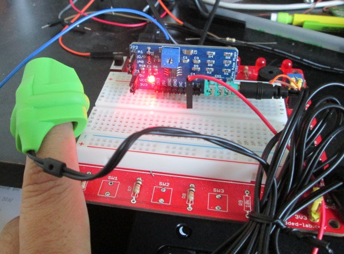
The Easy Pulse Plugin circuit is tested with a 5V power supply. The HRM-2511E sensor is worn on the tip of the index finger and the signal waveforms at various stages of instrumentations are analyzed using Digilent's Analog Discovery tool, which features a 2-channel USB oscilloscope.
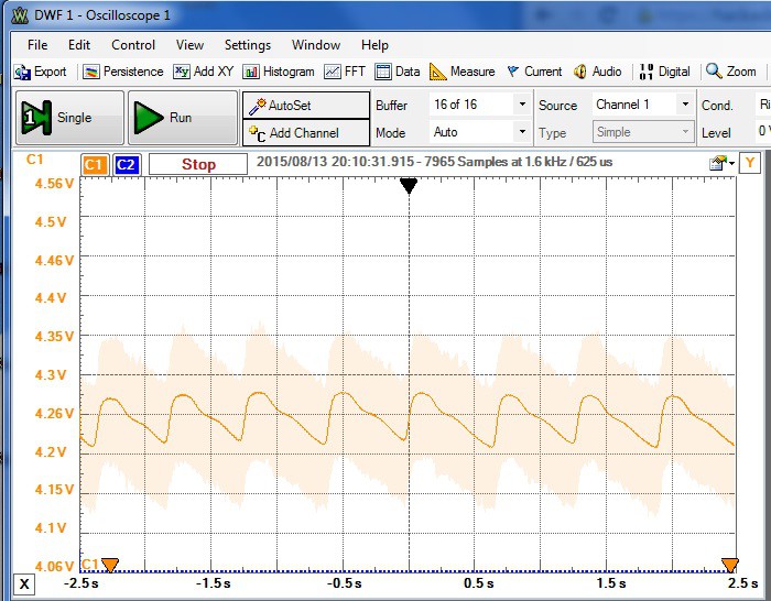
 The following figure displays the raw PPG signal output from the photodetector. The raw PPG signal is very noisy, as can be seen as a fainted image in the background of the main waveform, which is an averaged version of the raw signal processed by the Analog Discovery tool PC software. The signal is weak with a peak amplitude of ~60mV. The Sytolic and Diastolic peaks can be easily seen in the averaged waveform.
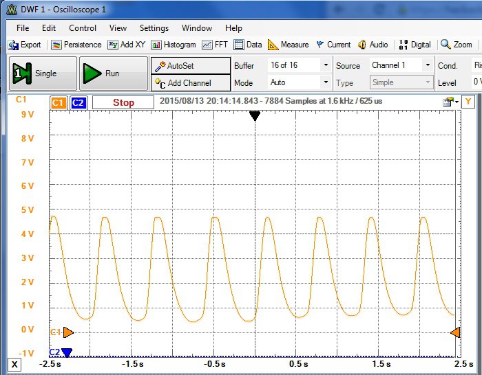
After two stages of amplification and filtering, the processed PPG waveform looks very smooth and exhibits a large dynamic range. The resulting signal thus looks perfect for a microcontroller's ADC input channel for further processing.
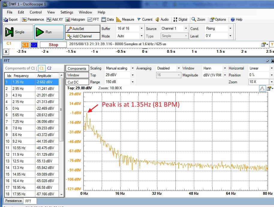
The Analog Discovery oscilloscope software tool also provides the Fast Fourier Transform (FFT) view of the input signal. The following picture shows the FFT output of the final PPG signal. The FFT peak corresponds to the fundamental frequency component of the PPG waveform, which is the frequency of the heart beat. In this example, the peak occurred at 1.35Hz, which is equal to 81 BPM (1.35*60).
Discussions
Become a Hackaday.io Member
Create an account to leave a comment. Already have an account? Log In.