 Göran Nordahl
How do you tackle indoor navigation so accurate that you can keep a robot in a confined area? We needed to complement dead reckoning with an absolute sensor. Like GPS but indoors and with a higher accuracy. The same problems exist in GPS denied environment or where the GPS is just not reliable enough. A lidar could be used against an existing lidar map or with landmarks identified in some way. But we wanted an alternative. Thus, absolute location without GPS: Local Positioning System (LPS).
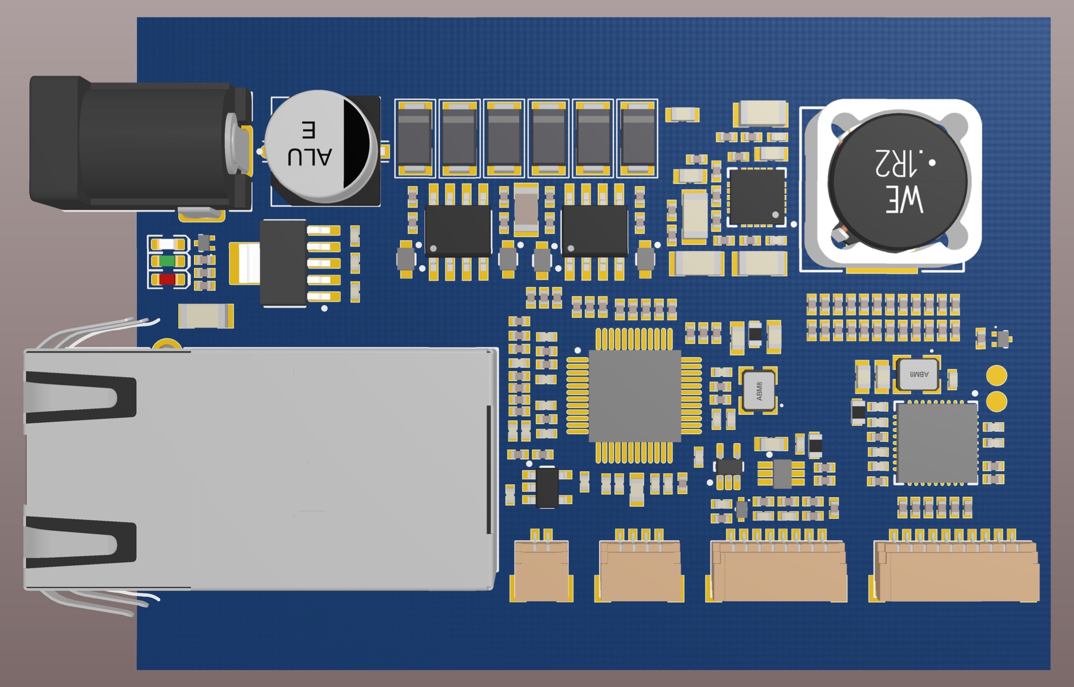
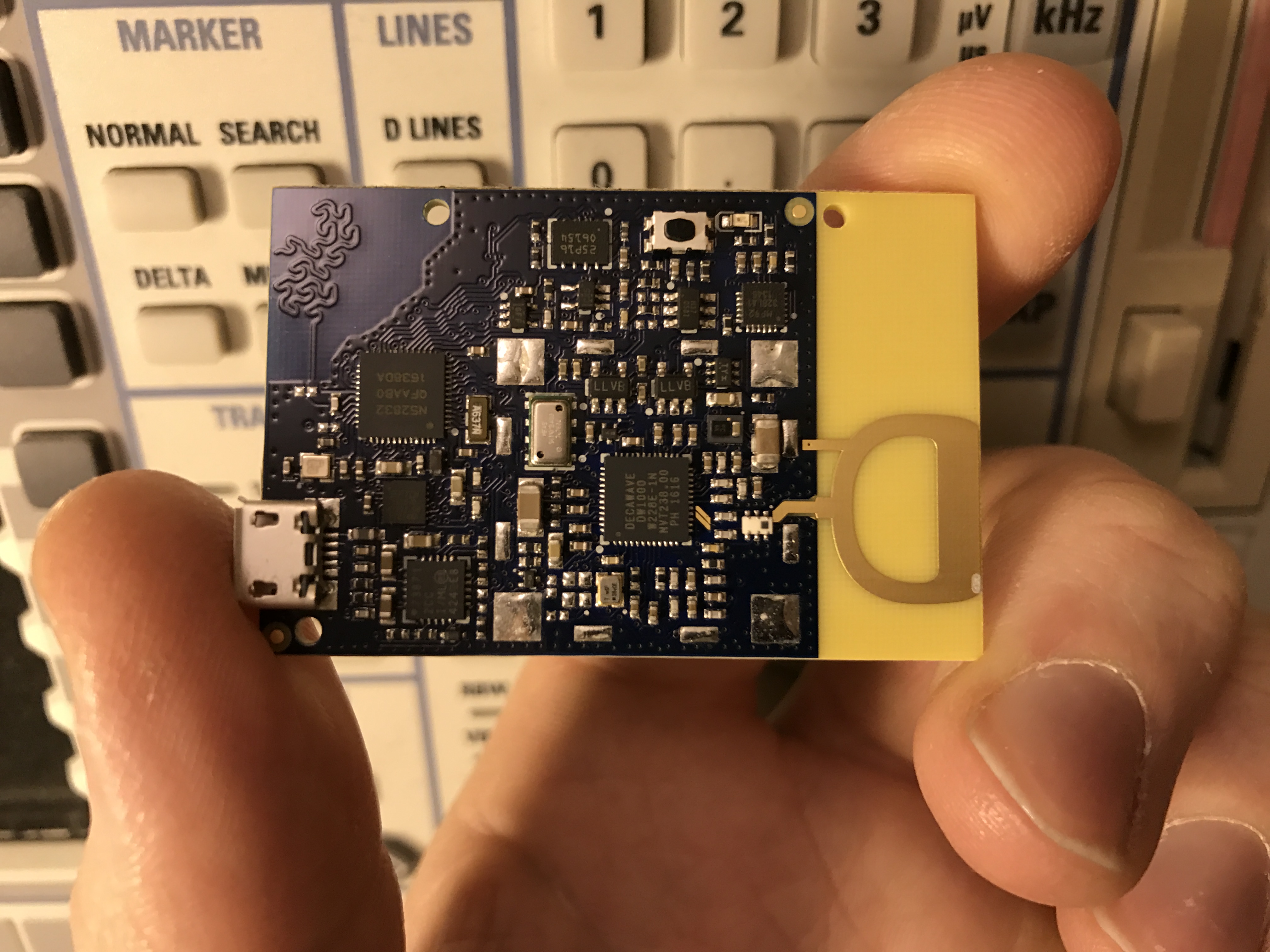
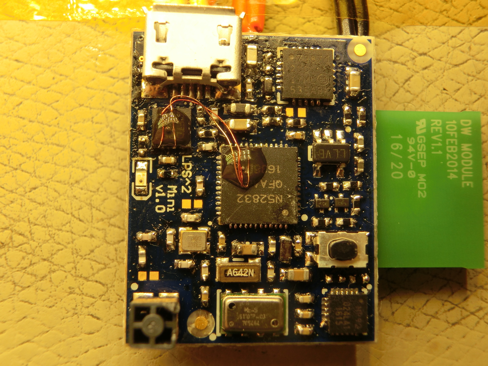
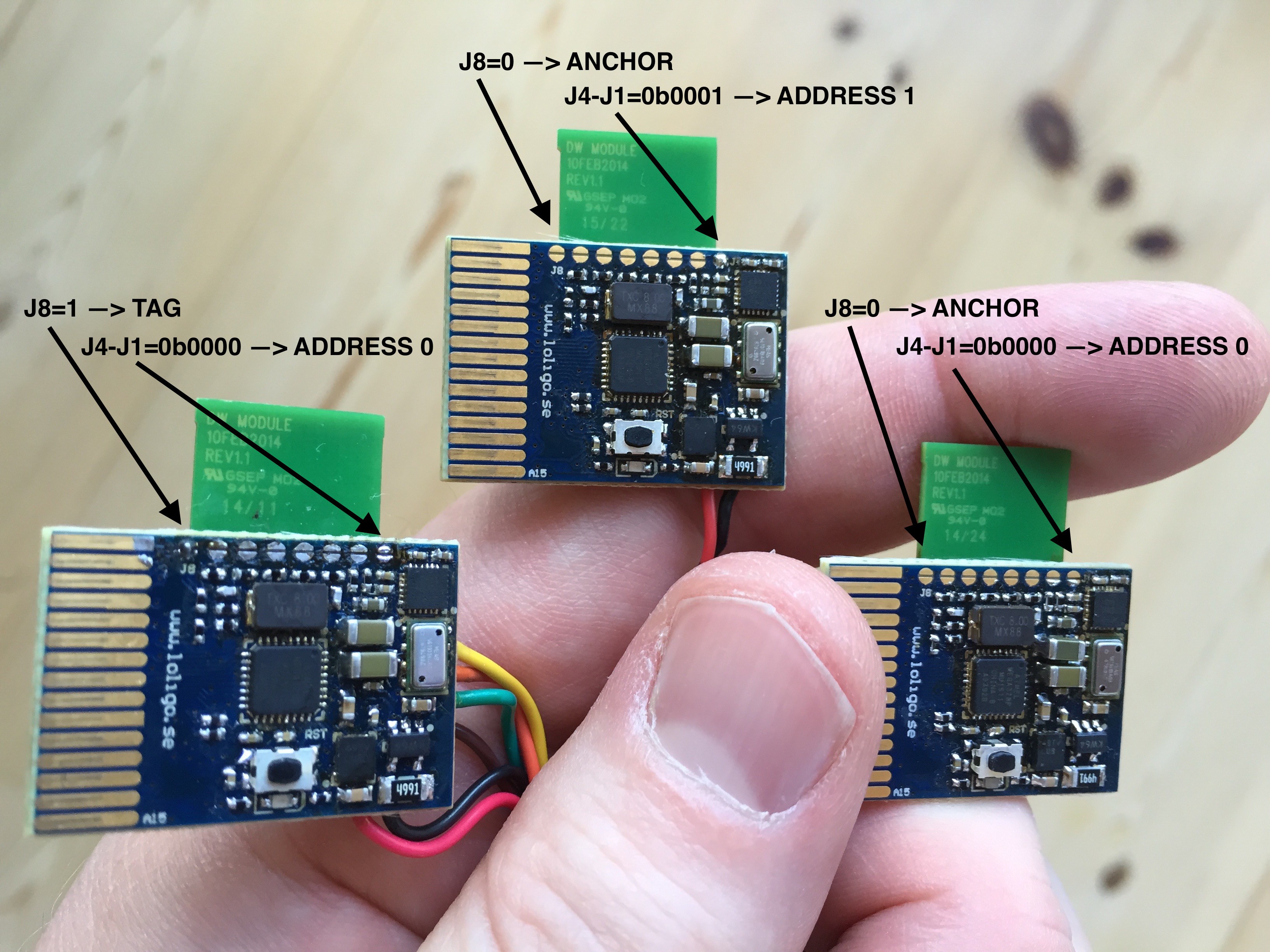
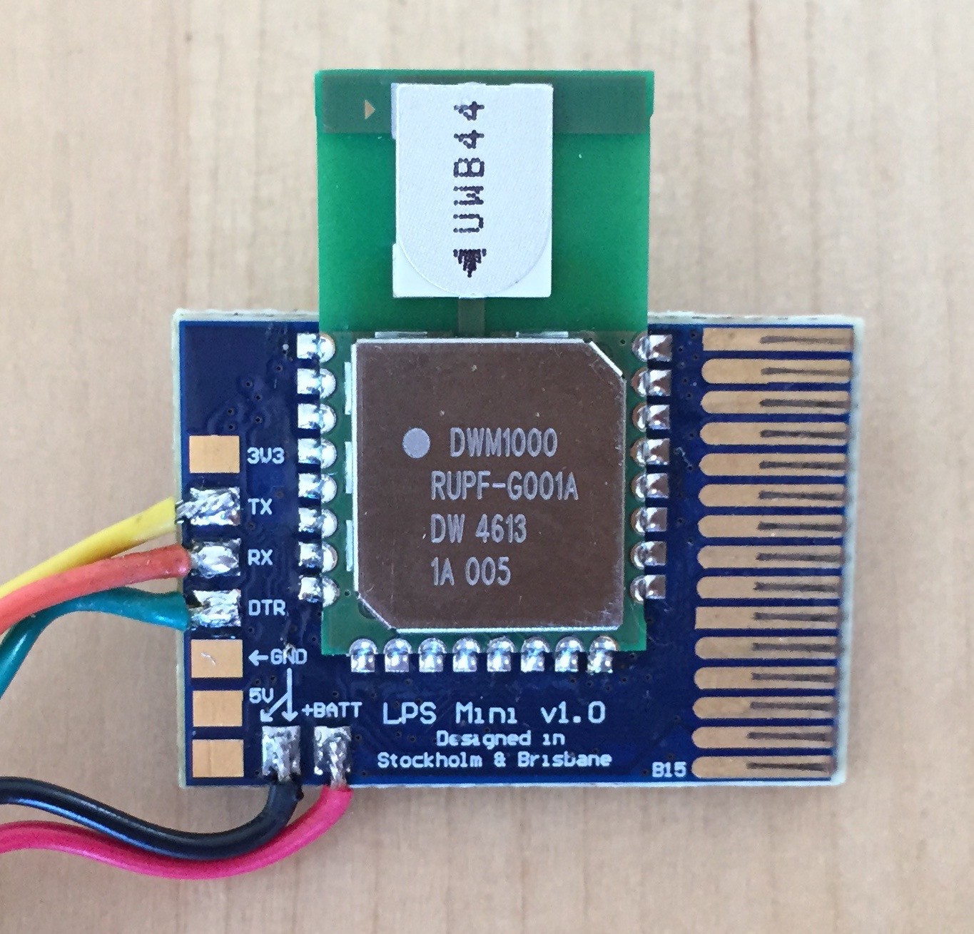
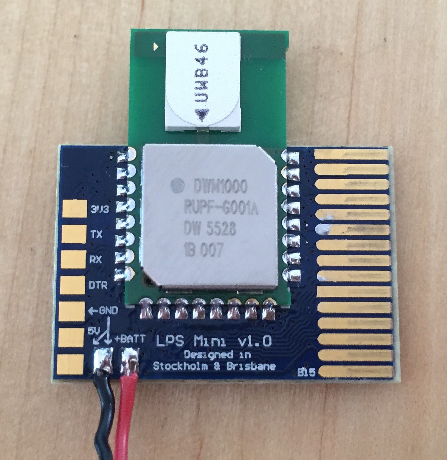
The project is centered around the DW1000 chip - an ultra wide band radio chip from DecaWave. This chip has excellent reflection and second path rejection and do (for most of the time) give you the shortest distance between two of the nodes. Using one or a few nodes (tags) on the thing we want to locate and a number of stationary nodes (anchors) of known location we can get the distance between each tag-anchor nodes. This is the same way that GPS works - by estimating the distance between the GPS receiver and the different satellites. From these distances, or ranges, we can estimate the location. Combined with inertial and dead reckoning you can get a very good estimate over time of where you are located relative to the anchors.

 Andy
Andy
 Paul Andrews
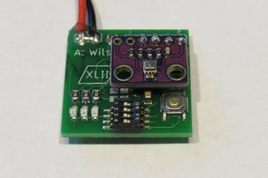
 alnwlsn
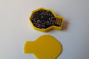
 Max.K
Max.K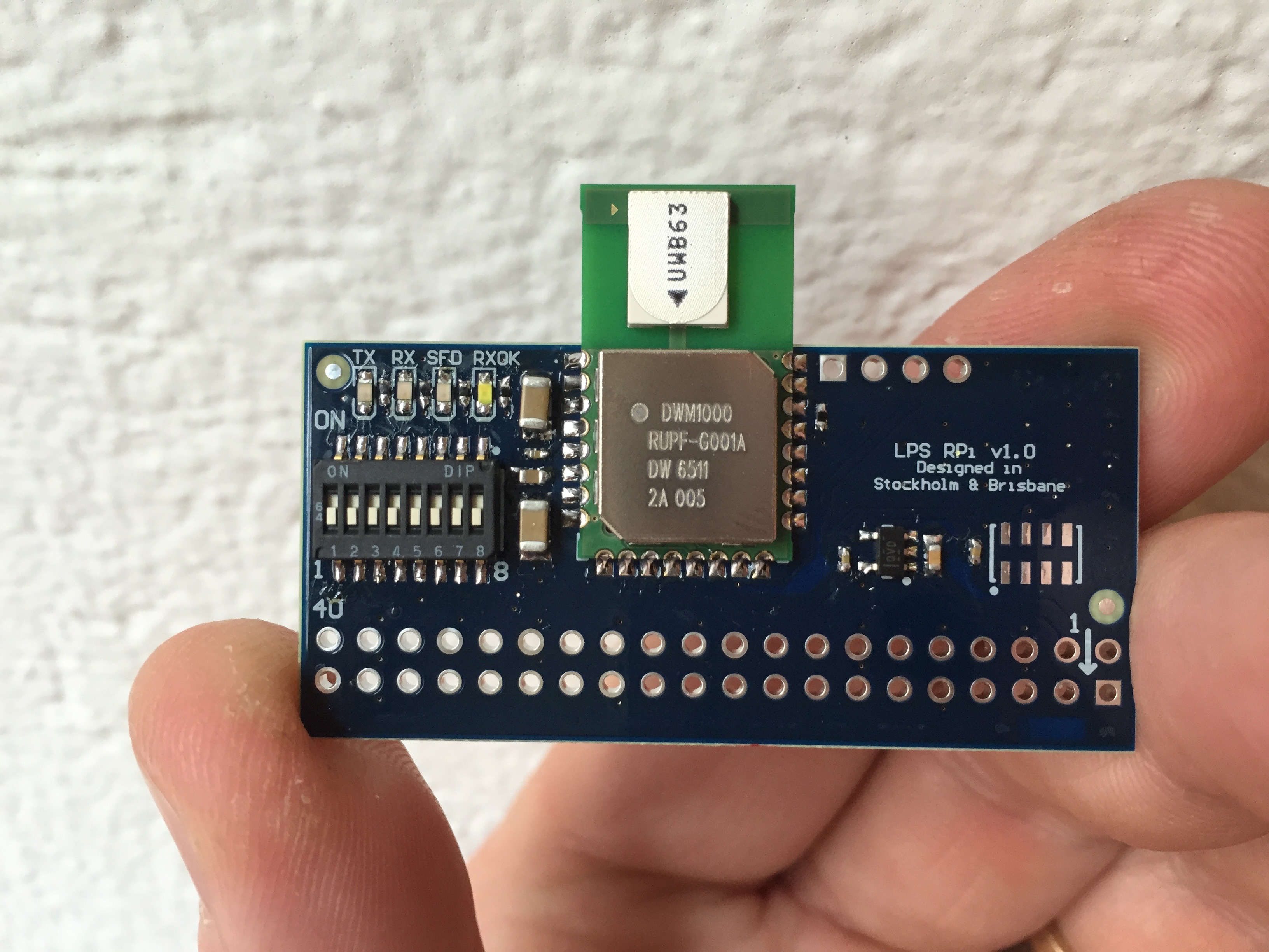
Nice work.
Why not add GPS to a few so the system can get position locks on a couple locations using two devices on areas with coverage, and then use those locations for relative calculations to deduce the remaining base stations real latitude and longitude as best as possible.
This would make possible to integrate this with GPS maps, creating a seamless solution for outdoor/indoor position detection, which is very nice :)