0%
0%
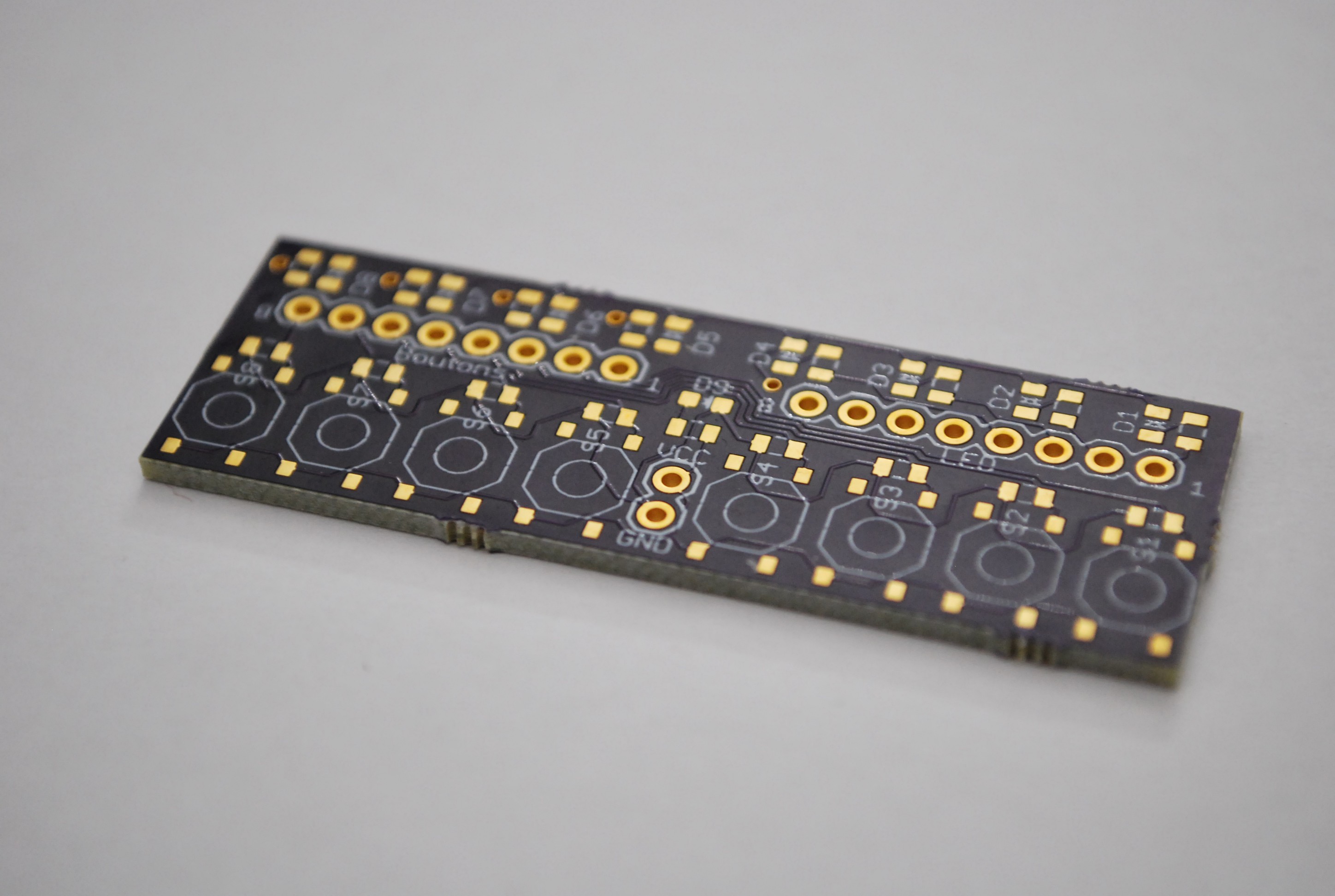
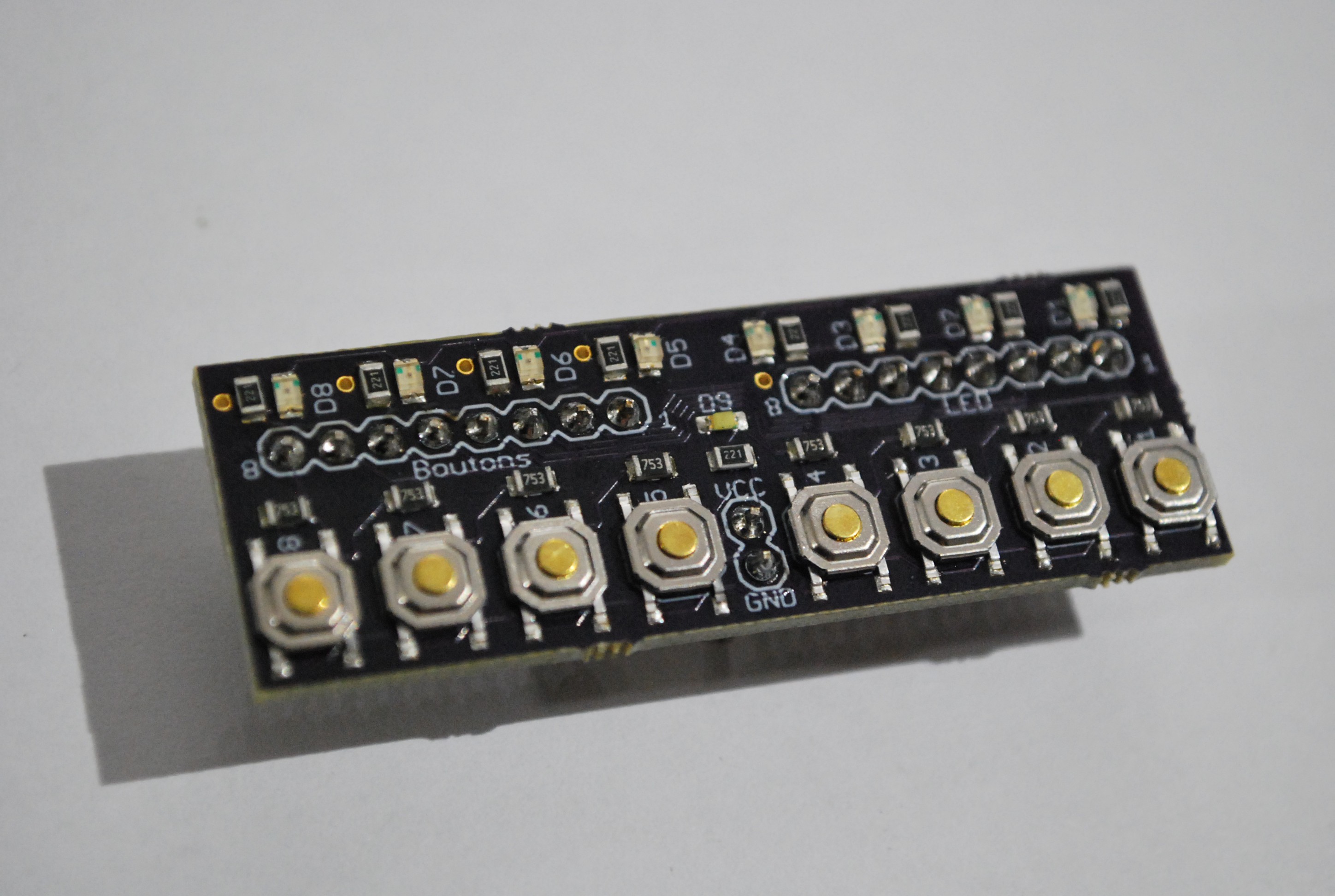
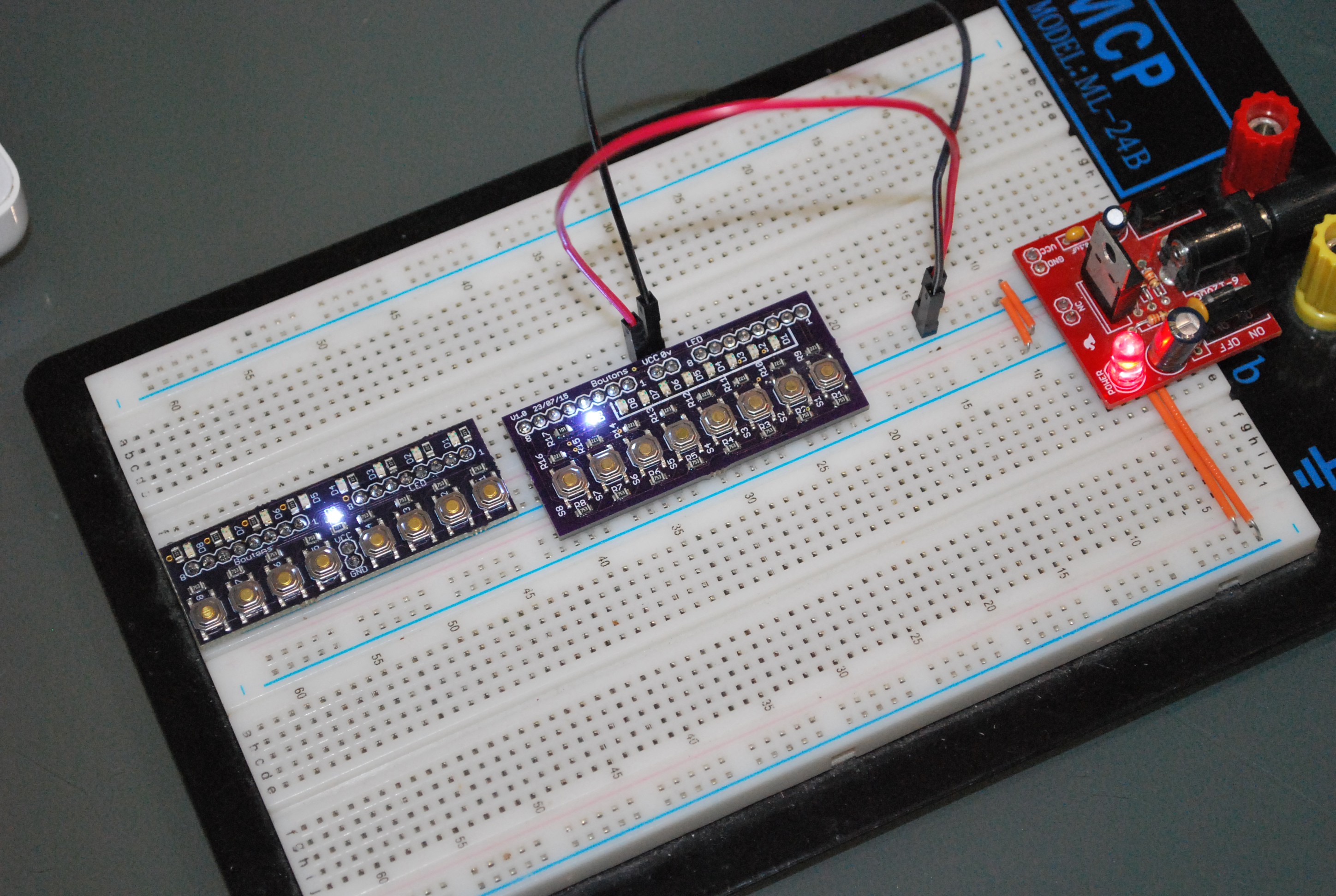
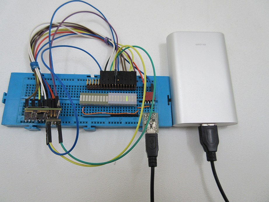
8 buttons 8 LEDs breakout board
Another compact, breadboard friendly breakout board with 8 pulled-down buttons and 8 LEDs.
 Charlie
Become a Hackaday.io member
Already have an account? Log in.
Just one more thing
To make the experience fit your profile, pick a username and tell us what interests you.
Pick an awesome username
hackaday.io/
Your profile's URL: hackaday.io/username. Max 25 alphanumeric characters.
Pick a few interests
Projects that share your interests
People that share your interests


 Dave's Dev Lab
 drewrisinger
 sbi.gaijin
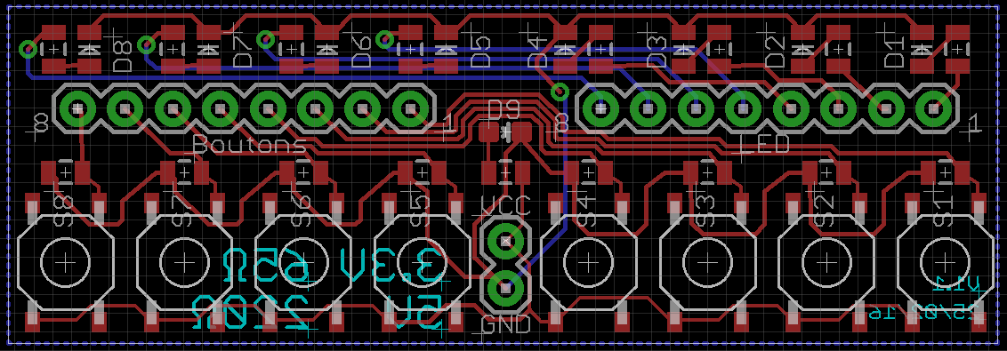
Nice design style. There is a link to the gerbers and BOM? Thanks in advance!