Close
0%
0%

Shower Metronome

Minimize shower day dreaming, conserve a bit of water.

Similar projects worth following
The goal of the Shower Metronome is to minimize day-dreaming while showering, keeping you on time for work, saving money on your water bill, and conserving a bit of water. A small battery powered enclosure will be mounted on the shower door frame or near the shower curtain rod. A magnet will be added to the door or shower curtain. The Shower Metronome will use hall effect sensors to sense the magnet and start the metronome ticking. The ticking will increase in frequency as time passes to encourage completing showering in a reasonable amount of time.

The Shower Metronome project idea was conceived years ago. Not a very glorious, exciting, or technically challenging project and therefore no real motivation to pursue. The “We have a problem: Shower Feedback Loop” post almost got me started on the project. Some of the comments related to how little residential usage contributes to overall water consumption seemed to make the water saving aspect of the project somewhat irrelevant. No real effort was applied until the “Homework for this weekend” post. The challenge to build something over the weekend and enter the 2015 Hackaday prize contest was accepted.

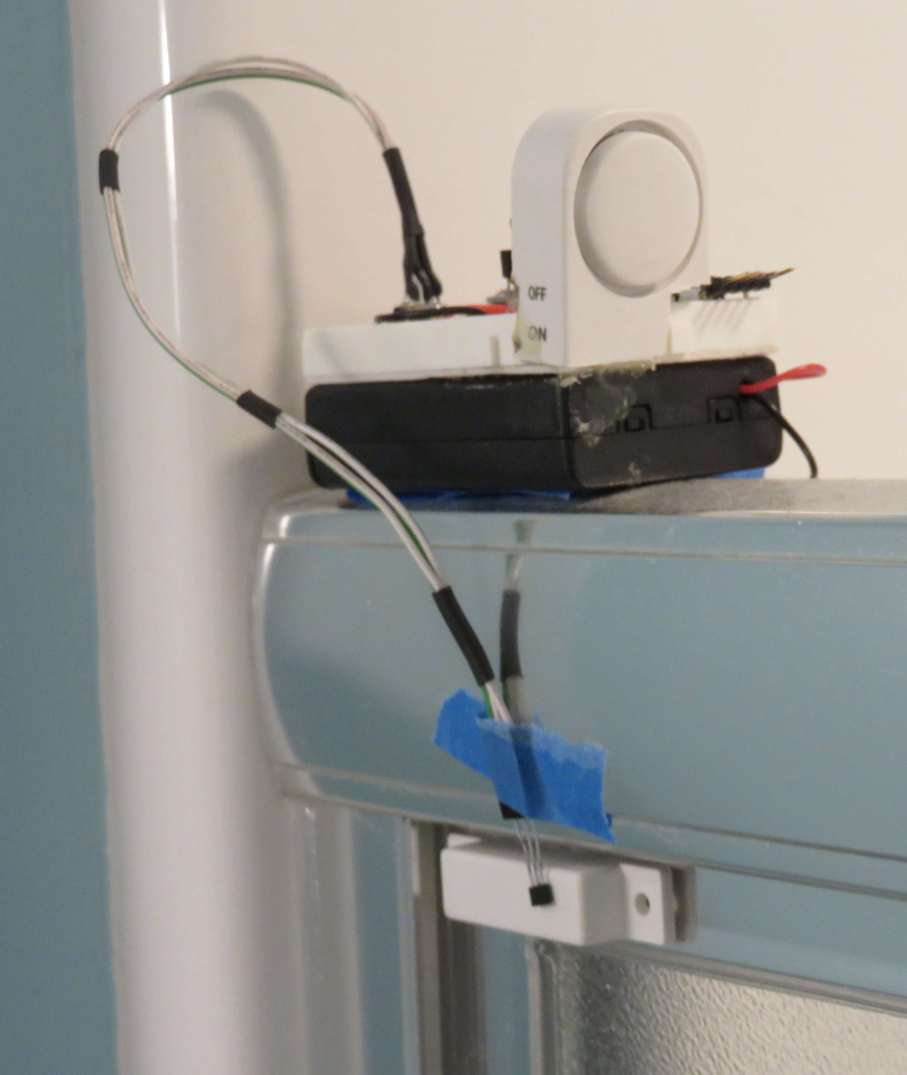
One of the design goals of the project was to keep it simple. No cutting into the plumbing for installation, no internet connection to tweet showering status, no vision system to automatically identify the family member taking the shower in order to create a water usage metric. Hopefully the Shower Metronome becomes more useful as a training device to break excessively long showering habits and not something that becomes a permanent bathroom fixture.

A fellow engineer questioned the marketability of the device. We both doubted anyone would spend $10 on one of these as an impulse purchase at the hardware store. A few other options to commercialize the Shower Metronome came to mind as it was discussed over a few more beers; hotel chains could see substantial savings and government sponsored conservation programs that send households these for free.

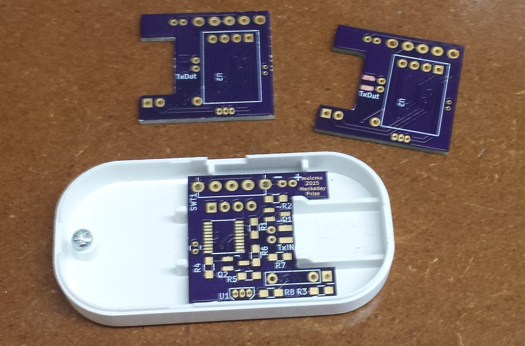
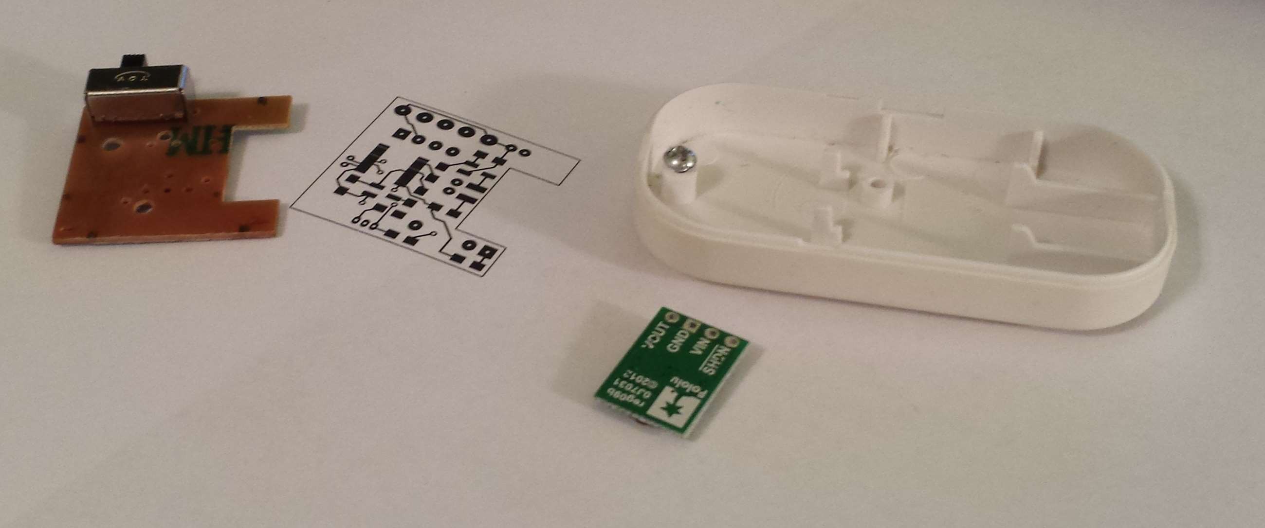
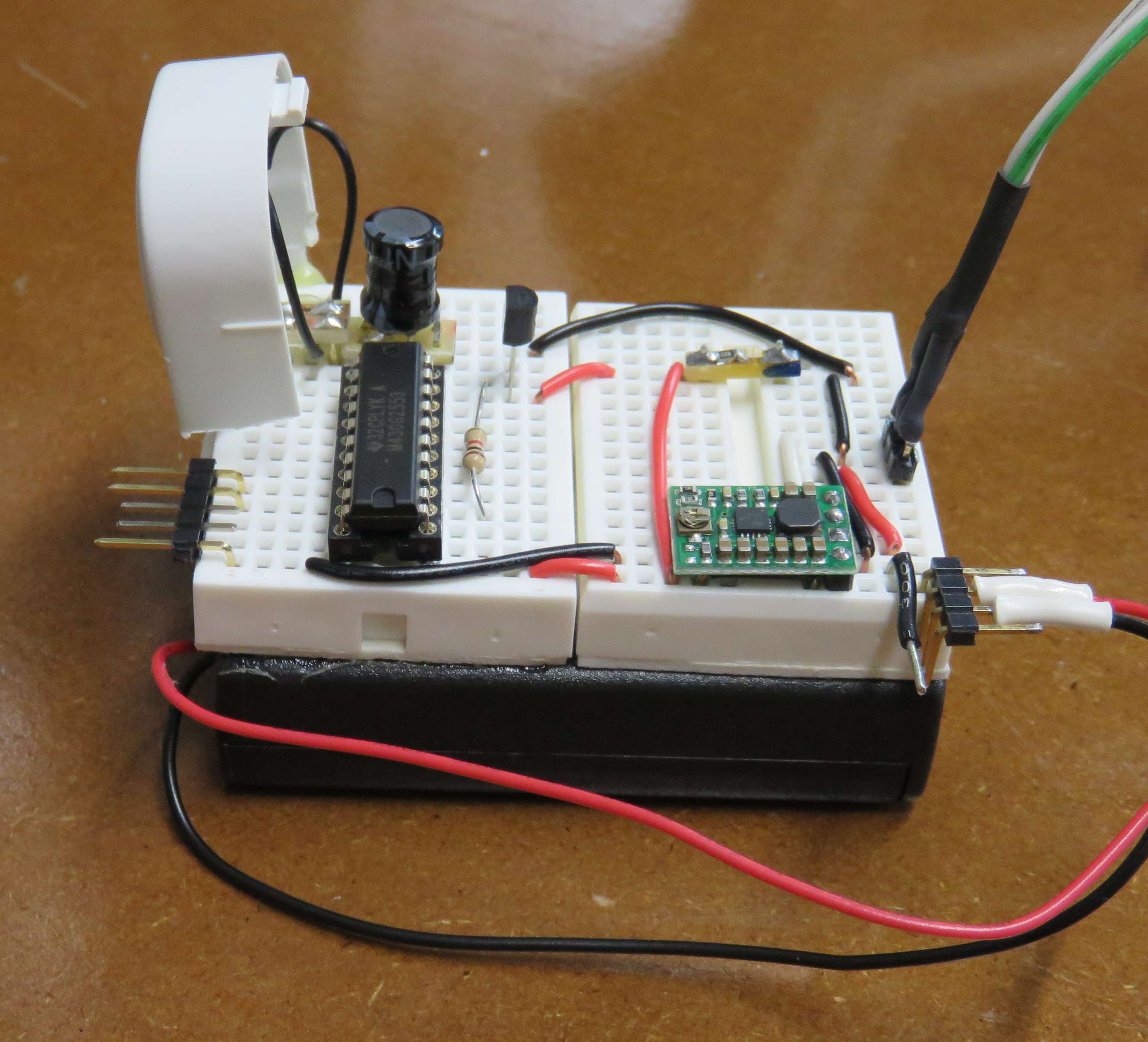
A functional prototype has been built to test the software and get initial feedback on the effectiveness of the beeping in reducing day dreaming while in the shower. So far it seems prosiming in reducing the amount of day dreaming.

  • 1 × IntrudAlert Door/Window Alarm I had four of these in the junk box, I assume similar units can still be purchased. The enclosure is reused along with the power switch, speaker and transformer that drives the speaker.
  • 1 × TI MSP430G2553 20 pin PDIP used in the prototype. 20 or 28 pin TSSOP package will be used in final design.
  • 1 × Pololu S7V8A Adjustable Step Up / Step Down Voltage Regulator
  • 1 × Allegro A3214 Low power Hall-Effect Switch
  • 1 × 2N3904 NPN BJT

View all 7 components

  • Final Operation

    mulcmu12/04/2015 at 13:53 0 comments

    PCB was populated and MCU programmed successfully. Found an annoying bug in the TI Grace software when changing the PWM output pins around. The GPIO resistor enable bit remains set and was screwing up the output signal.

    Still need to get some quality photos of the final PCB.

    Demo video of operation, need a stronger magnet or need to offset the magnet a little bit due to the shower door being recessed.

  • PCBs Arrived

    mulcmu12/04/2015 at 13:22 0 comments

    PCBs arrived. Made one mistake on the solder mask for the transformer connection. Scrapped it off okay. Fit in the case perfectly.

  • PCB Ordered

    mulcmu10/04/2015 at 00:52 0 comments

    Finished the PCB layout. The Pololu regulator will be mounted under the main PCB. There is a plastic stand off that will need to be removed for clearance. There was a corresponding hole on the PCB to secure it to the case but none of the ones I've opened so far have been screwed down. Other layout options got the module too close to the supports around the edge of the case.

    The speaker drive transistor was changed from a NPN BJT to a n-Mosfet, 2N7002. Almost got burned by the SMD package pin numbers being different than the TO-92 case pinout. I left the base resistor in the design to support going back to BJT. Initial testing with the 2N7000 was a bit louder on the volume. A series resistor was added with the transformer input to cut the volume down a bit.

    Added the battery voltage monitor back into the design. The resistor divider for the ADC input is also controlled by a 2N7000 to minimize standby current consumption.

    Forgot to add in a footprint for the SMD hall effect sensor, those will have to wait until revision 2.

  • Functional Prototype

    mulcmu09/21/2015 at 03:07 0 comments

    The functional prototype was finished during the week. Just finished the Semifinals video. Not real pretty but it works. (hasn't gotten too wet yet...)

  • Reverse Engineering Continued

    mulcmu09/15/2015 at 01:43 0 comments

    The mystery part was identified as a transformer.

    When it was removed from the original PCB one of the enamel wires came loose from the case pin. This resulted in an intermittent/partial connection and a lot of frustration during testing. This was fixed with an extra glob of solder.

    An MSP4302353 replaced the G2211 in the breadboard. The G2211 only has one timer, plan on using two timers to control frequency and length of the chirp. Speaker operation was tested from 100 Hz to 10 kHz with 50% duty cycle. NPN BJT was used for high side switch. The original device used a low side switch. Volume was adequate through most of the range, started to drop off around 8 kHz. Going to proceed with the design re-using the transformer from the window alarm.

    The RMS voltage ratio seemed to be consistently between 5:1 and 6:1.

  • Reverse Engineering

    mulcmu08/28/2015 at 15:21 0 comments

    The original IntrudAlert PCB has a 4 pin mystery device that drove the speaker element.

    One leg is connected to the battery positive, one leg is connected to a transistor (assumed) controlled by the epoxy blob that switches to the battery negative. The other pair of legs connect to the piezo element. A search for XILIN turns up a manufacturer that seems to make a bunch of these windows sensors.

    Connected scope probes to the piezo legs:

    Not the waveform I was expecting to see, and especially not the 100V per division setting. Promptly disconnect probes and then double checked the 10x setting on probes. Looks like the peaks are indeed greater than ±100 volt. This makes sense that more voltage is needed for more volume.

    I think next will be to test a voltage multiplying circuit or driving the 4-pin device from the MSP.

  • Parts Ordered

    mulcmu08/28/2015 at 12:25 0 comments

    Ordered a few of the A3214 hall effect sensors (SMD and SIP) and some of the 20-pin and 28-pin TSSOP MSP430G2553.

  • Battery Life

    mulcmu08/26/2015 at 02:13 0 comments

    Started to look into the battery life this evening. Planned to have two hall effect sensors one for shower door and the other for shower curtain orientations or maybe 4, 2 for each orientation. The best case A3144 supply current draw is 4mA per the datasheet, less than 2 days of stand-by for just the sensors with 150 mAh LR44 coin cells.

    Found a similar Allegro A3214 with a 6 μA (typical) supply current (datasheet 22 μA max is still better than 4mA). Will need to order some of these. The supply voltage range is also reduced from the A3144 that happened to work under the minimum data sheet supply voltage. Plus these ones are not magentic pole sensitive.

    The MCU will be in low power mode most of the time so 1 μA or so.

    A buck-boost converter will maximize usable battery life. The energizer cut off voltage was .9, so 2.7V for 3 cells. Might look to see if I can find a drop in board that will work and fit in the case.

    Another option is to power the hall effect sensors direct from the battery. When magnet is detected they would enable power to the MCU and rest of circuit. The buck - boost converter could remain in shutdown mode saving more power. Prototype with a linear regulator should even get decent battery life.

  • Speaker Testing

    mulcmu08/24/2015 at 02:08 1 comment

    Tested operation of the cannibalized enclosure speaker. MCU Pin 4 configured for PWM output. Resistor divider used for one leg of the speaker for 1.65V constant reference. The other leg hooked up to the PWM signal. Worked okay connected to the MCU pin with 100 ohm resistor. Need to decide how to drive speaker via transistor and test before starting PCB layout.

  • Entry

    mulcmu08/16/2015 at 22:45 0 comments

    Created and uploaded video of prototype:

    Created system design document:

    https://github.com/mulcmu/ShowerMetronome/blob/master/design document.pdf

View all 16 project logs

Enjoy this project?

Share

Discussions

Henti wrote 10/20/2019 at 14:48 point

  Are you sure? yes | no

praetorian wrote 09/10/2015 at 23:37 point

A suggestion perhaps to add one of those hydro-dynamo generators inside the spout so that the water flow itself powers the device. An example of what I'm talking about are those LED faucet lights that indicate temperature of the water. A video of one being pulled apart is here so you can see the exact component I'm referring to (It's the bit on the left in the preview). Best of luck with your project!  

  Are you sure? yes | no

Buzz wrote 09/07/2015 at 09:12 point

I'm more likely to go for something like the "shower Shortener", as it's smarter and already available: http://davinda.com.au/index.php/shower-shortener/

  Are you sure? yes | no

Does this project spark your interest?

Become a member to follow this project and never miss any updates