 Nickcasio
With the mechanics now sorted it was time to consider the electronics, but before laying out a schematic a flow chart of operation had to developed.
The initial flow and sequence of events are as follows:
- Swing Arm starts in the up position
- User places tea cup full of boiling water under the swing arm additionally use wraps tea bag string around swing arm.
- User depressed Set Button, swing arm moves to the down position dunking the tea bag in the boiling water
- Tea bag remains in the boiling water until the desired time has elapsed (default 3mins), Swing arm moves to the up position
- At any time the reset button can be activated to move the Swing Arm up and tea bag out of the boiling water.
The flow chart
helped identified the requirements for the electronics, added
features where deemed necessary to meet the needs of the end users,
eg vision impaired users require tactile buttons and audible tones,
hearing impaired users would require visual cues and of course all
users could benefit from all these additional features. Adding
features increase the overall cost, and keeping cost down was
important. Trade-offs between features and costs were made with the
addition of 4 surface mounted lights (LEDS) for visual feedback,
tactile push buttons selected and a piezo buzzer added for visually
impaired users (Below).
The Brains of the operations is and Arduino Nano PCB, Atmel 328p; the nice thing about these low cost circuit boards is that they already have suitable features reducing the overall bill of materials (BOM) such as voltage regulator, usb connector for debugging. And also facilities STEM because the student change the parameters of code in the ARDUINO IDE / or using a text editor and GCC. 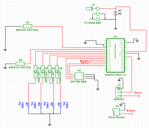 National Instruments
Multisim™ was used for
the schematic capture, which then was transferred to Ultiboard™
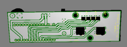
for layout. Circuit Board Layout involves mechanically places the
individual parts such as push buttons, lights and other components
drawing tracks that link all the parts electrically together pictured below.
National Instruments
Multisim™ was used for
the schematic capture, which then was transferred to Ultiboard™
for layout. Circuit Board Layout involves mechanically places the
individual parts such as push buttons, lights and other components
drawing tracks that link all the parts electrically together pictured below.
Discussions
Become a Hackaday.io Member
Create an account to leave a comment. Already have an account? Log In.