 Alexander Tuxen
- Plating bath: Original Thinktink recipe w/o any additives (just distilled water, H2SO4, CuSO4 and a drop of HCl), at room temperature with bubble agitation.
- Pulse current: 19/1ms pulse duration, 1/3 pulse amplitude, 2A/dm² average current density (roughly 20ASF)
- Anodes: Copper heating pipes (I might even have grabbed phosphorized copper pipes by accident)
- Plating time: ~3h
- Added copper thickness: ~50µm
- Copper surface: bright and dull
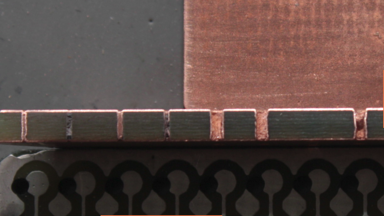
I made a few cross sections by cutting off a slice of a test board and sanding it down with 600 grit sandpaper. Here is the result:
This is a close up of a 0.3 hole I made with an improvised usb microscope. No Idea what magnification this is.
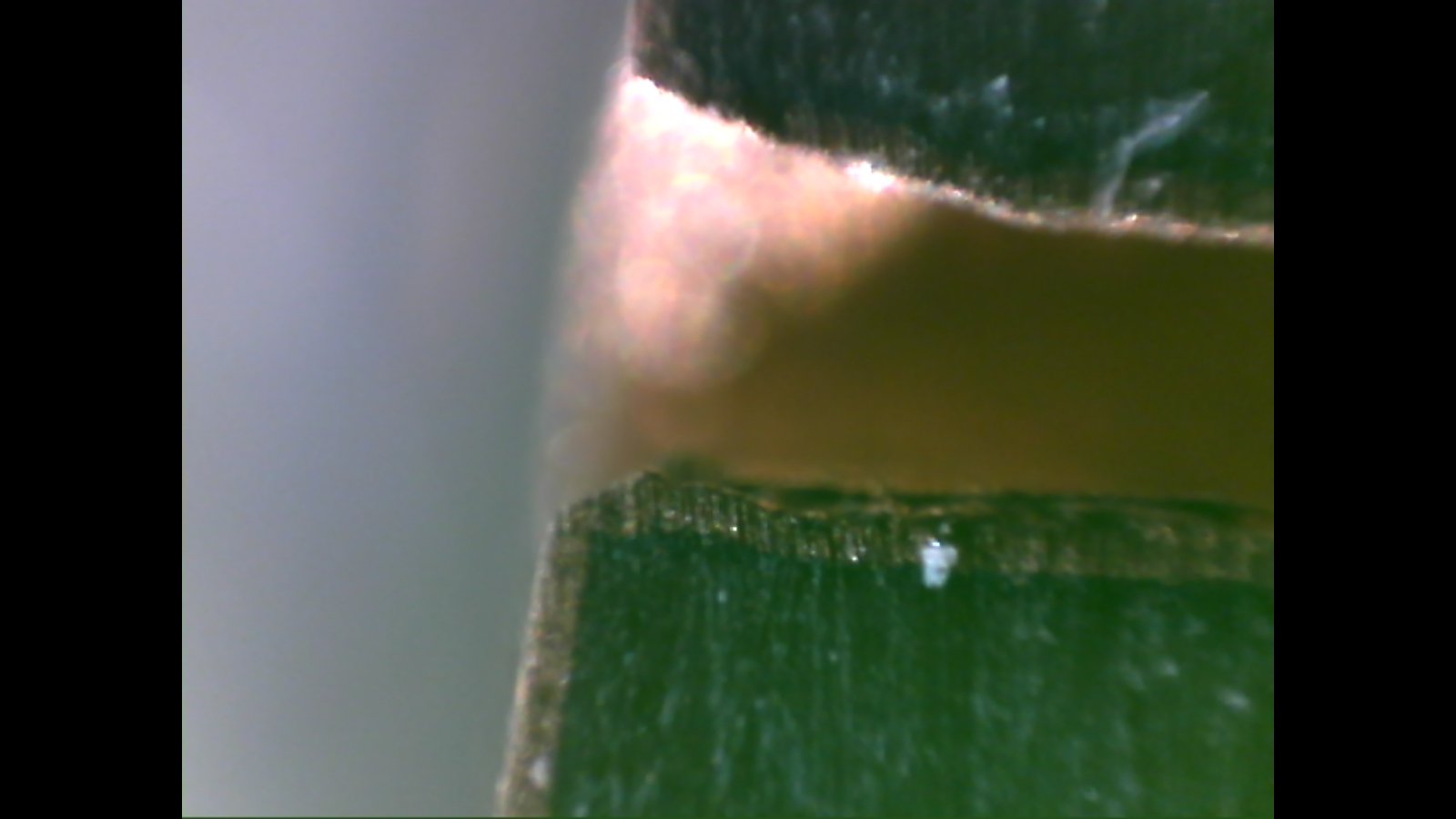
It's clearly visible that the copper on the hole walls is at least as thick as on the surface, which supports the theory that pulsed reverse current improves throwing power. If you look closely and with a bit of imagination, you can even see the thin black layer of conductive ink between the copper and the substrate.
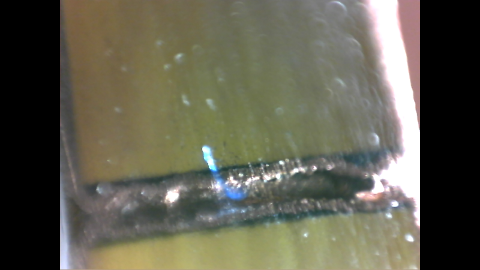
Here is another one showing the whole barrel:
Well, that's it, I'm done. I could muck around with additives like PEG and try to get a shiny surface, but why bother? Plating holes works amazingly well, and the following process steps don't care about looks. In retrospect, I must say the trickiest part was getting the conductive ink right. The conductive screen printing paint from Peters is definitely the right tool for the job, but might be hard to get in some parts of the world. But then, there might be other things available, like Higgins Black Magic ink, which I hear works very well, also. The PCB for the current source only took that long because I was experimenting with other process steps which screwed up a few tries.
The code, schematics and layout for the current source are in my github, as well as the CAD files for the guts of the process tank. So go and buy a PE food container, copper sulphate and a bottle of battery acid, fire up your hackerspace's laser cutter, throw together a current source, and plate your own boards!
Discussions
Become a Hackaday.io Member
Create an account to leave a comment. Already have an account? Log In.