 Adam Munich
Around the end of October, I finished up the design of all the plastic components which would house the electronics of a 200W x-ray system. It was now time to design those electronics!
Back in September, I had an idea of how I should go about doing this. The system would have to have, among other things,
- A means of charging lithium ion batteries
- A means of monitoring and protecting those batteries
- A user interface
- A radio for remote operation
- A boost converter capable of 300W pulses
- An H bridge
- A power transformer
- A voltage multiplier
- A voltage source for the cathode
- Safety features!
After careful re-evaluation of my older schematic, I deemed it unsuitable for the job at hand. Particularly, because it would take "too much tweaking" to get operating reliably, given that, the STM32 would be doing almost all of the work. This might seem counter-intuitive to some, but the job just felt simpler to do with op amps instead.
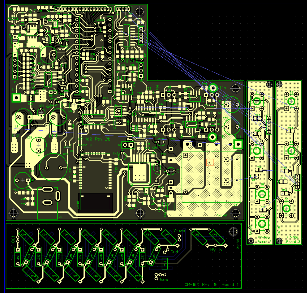
Revision 1: "Hey this could work"
Over the course of a week, I chose low-cost parts and tossed them onto the board, in a way that felt like they'd work without much incident. Like most of my projects, I didn't bother drawing a schematic, and instead just went with the signal flow, so to speak.
The analog electronics are all done with stand-alone parts, and, to synchronize everything and provide a UI, I chose to use a Teensy 3.1 for this prototype. I did so, to allow me to use the fantastic OpenGLCD library, and save me the effort of writing a frame-buffer and object-oriented menu structure.
I managed to get it all done on a 2 layer PCB :-).

-
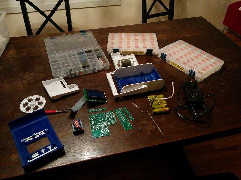
After receiving a copy of this board from Bay Area Circuits, I promptly put it together, only to discover that... it mostly worked! There were a few bugs however, and those were;
- Far too much switch bounce for the UI buttons, which are fed though a 7-3 multiplexer before entering the controller. Software filtering proved to be incapable of handling this.
- An unreliable cathode heater power supply, which would fail to start up on occasion due to the nonlinear resistance of a cold -> hot cathode transition.
- Issues with what proved to be a rather useless coulomb counter.
- A few noise issues here and there.
-
-
Board 2 solved these issues by adding filtering, better ground structures, an improved cathode power supply, and an IO expander to allow for some finer control of the analog beasts scattered about.
I also added a NAND gate, which hard-resets the PCB by pressing two buttons simultaneously on the machine.
-
-
However, it was not without its own problems.
- The coulomb counter still couldn't make sense of the noise while charging.
- The LCD panel sometimes would get strange white pixels in random places.
- The x-ray machine could fail in such a way that the beam could get stuck on.
I found the latter out the hard way, and had to cut wires next to a live x-ray tube (how fun).
Evidently, if the main micro-controller freezes, it's possible for pins to get stuck in certain configurations that ensure the power electronics are still operational, which. is. bad.
-
Board 3 solved these issues with a watch-doge timer, 3.3 to 5V buffers for the LCD panel, and a completely scrapped coulomb counter.
I added a fuse as well, after another incident caught everything on my board, but the bluetooth radio on fire. The radio simply got hot enough to melt itself off the pads, but curiously, still worked afterwards.
-
But alas, there was one more problem, and a rather obscure one too.
To generate my PWM train for the H bridge, I used a rather old IC, which had a duty cycle limitation of 45%. I didn't expect this to be much of a problem, but, to my dismay, the inability to switch at 50% duty cycle allowed for spurious oscillations to happen during portions of the x-ray burst. To fix this, I swapped the UC3524 IC for a more modern PWM controller.
And added LEDs to the buttons because reasons.
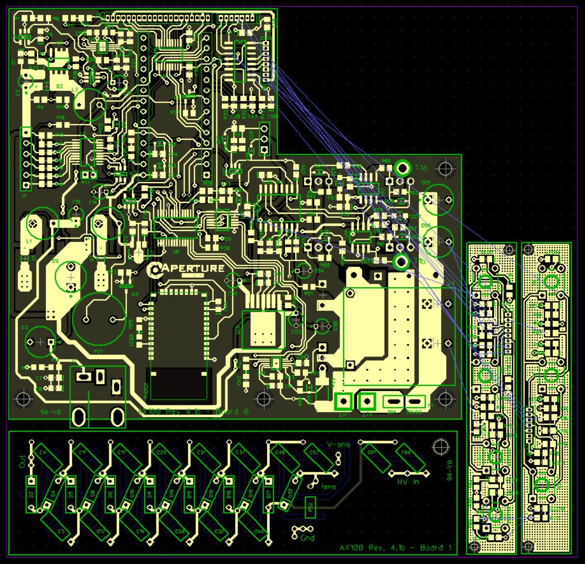
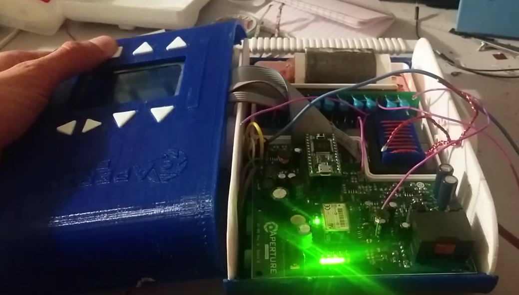
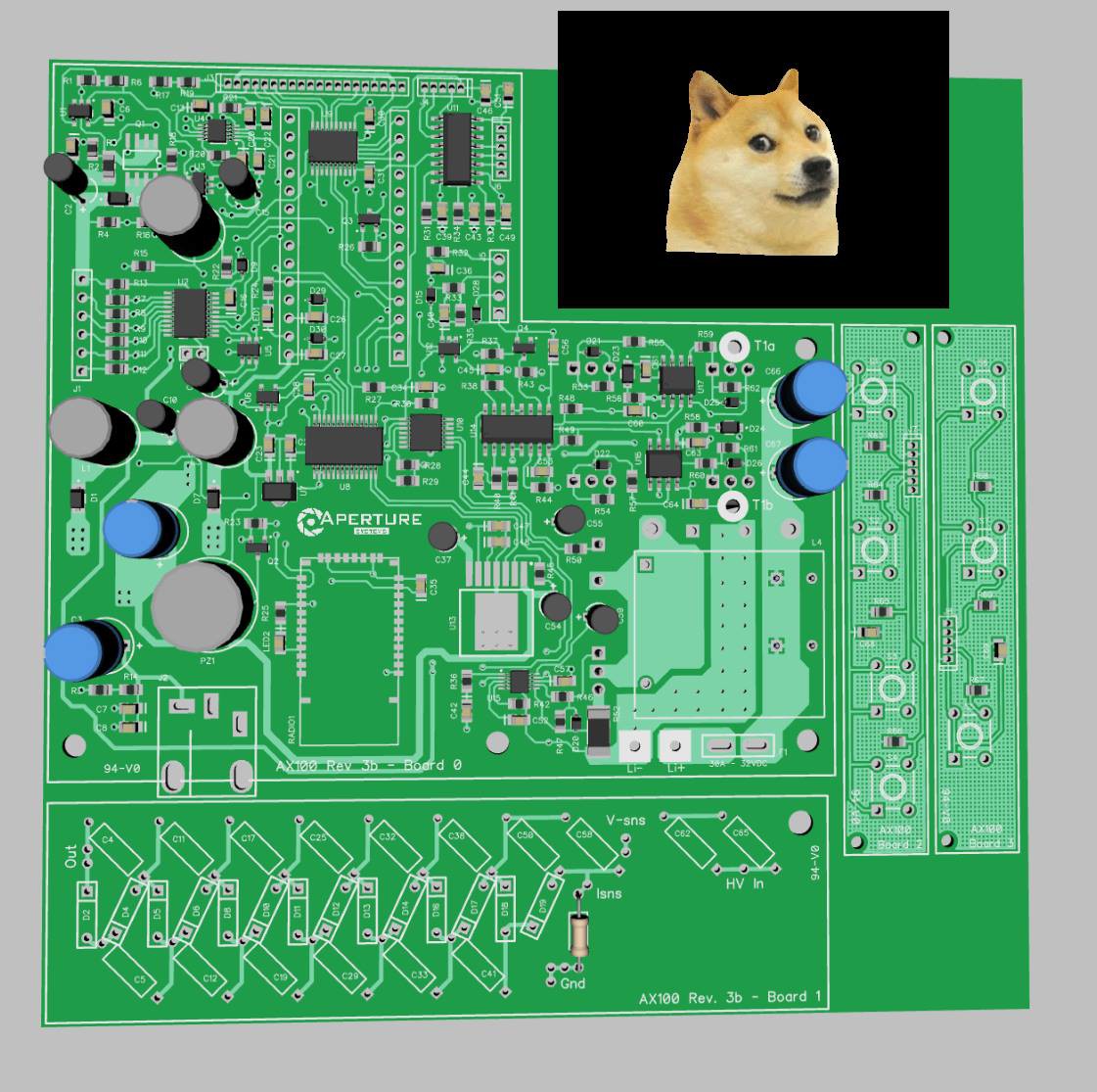
The 4th time was the charm :-)
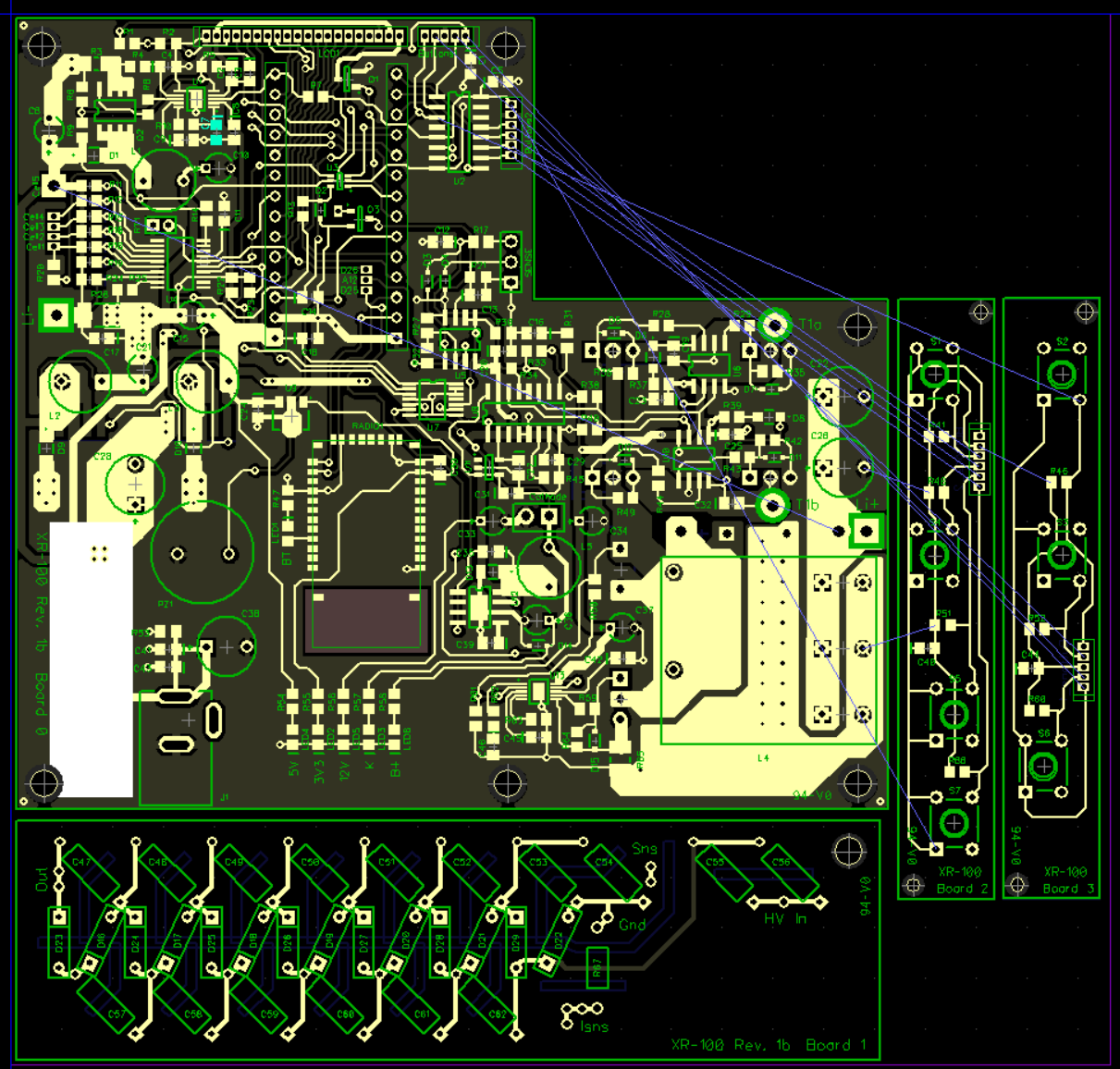
So, what's on the board?
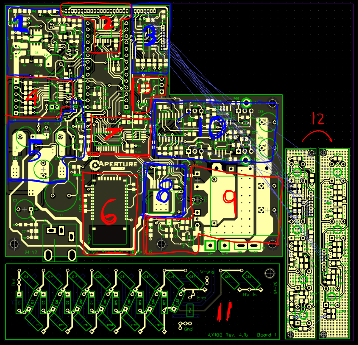
In no particular order...
- A current mode, or voltage mode (selectable) boost converter for charging the lithium batteries.
- Buffers for driving the LCD panel, and an LED driver for the backlight.
- UI button filters and multiplexer
- Battery management DAQ and analog switch
- Power rails, watchdog and standby power circuitry
- Bluetooth radio
- IO things to control the power electronics
- A buck converter for the tube's cathode
- A giant boost converter for the H bridge
- The few-hundred-watt H bridge
- A voltage multiplier
- Buttons and LEDs
- Feedback filtering to monitor the HV power supply
Board files:
https://drive.google.com/file/d/0BwIWrZZX8IW6U2trR2JNYU9ZRzA/view?usp=sharing
Parts list:
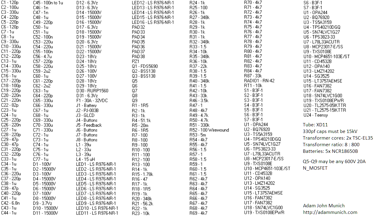
Have fun!
Discussions
Become a Hackaday.io Member
Create an account to leave a comment. Already have an account? Log In.