Joe George
DC LED Lighting System
This project will concentrate on developing a DC LED lighting system that can be retrofitted into existing home wiring systems. Goals of this system are to:
- Reduce the load from lighting to minimize the solar panels and battery capacity needed.
- Allow the system to be installed using the existing wiring in the home.
- Increase central control over individual fixtures for convenience and energy savings.
Background - The Problem
Current Wars
More than one hundred years ago when commercial power distribution was just beginning, two inventors Thomas Edison and Nicola Tesla competed to see who could better supply electrical power economically and efficiently.
Edison picked Direct Current (DC) for his first foray into commercial power distribution and Tesla picked Alternating Current (AC). It was a rancorous public battle; but Tesla was right, and not just by a little bit. AC power has the distinct advantage that its voltage can be easily increased or decreased with a transformer. This allows the voltage to be increased to thousands of volts for long distance transfers and then decreased to a usable voltage at its destination. Really high voltages decrease the power loss in the wires a lot.
Shocking Voltage
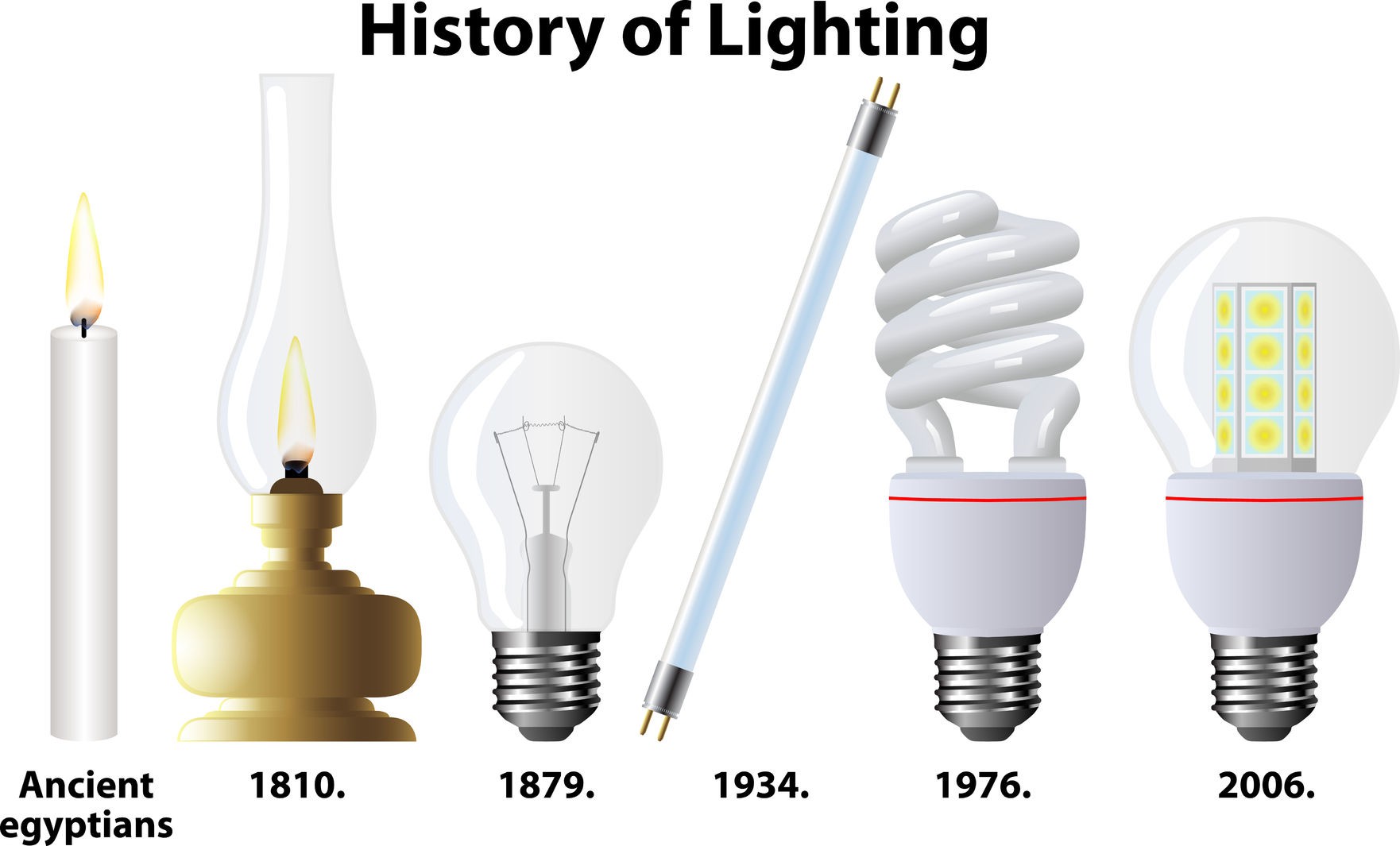
The original incandescent lights in the early days required a voltage of over 100 volts to operate effectively. This determined the minimum voltage that was used in homes and businesses. In some countries like the USA the minimum voltage chosen was only about 120 volts, while in Europe and many other places it was approximately 240 volts.
What our things need
So what has changed since the early days when these standards were set? In the typical home what things need AC power and what things need DC?
Some examples:
- DC - TV, Computer, Radio and pretty much anything electronic. Currently AC power is converted to low DC voltages in the unit.
- AC or DC - Refrigerator, Washer, Fans, and other things with motors could be designed to work with either.
- AC - Incandescent, Florescent, and other resistance lighting could be designed to use either but probably won't.
- DC - LEDs used for lighting gain no advantage from AC.
- AC or DC - Electric heating, water heaters, stoves, and other resistance heating. Either could be used but AC has the advantage since a higher voltage is generally desirable to decrease the size of the wires.
Solar is coming soon
As you can see a lot of the things in our homes use or could use lower voltage DC power, by why do we care? The efficiency of solar cells is increasing and the cost is decreasing at an exponential rate. The cost of power from solar will soon be less than the cost of grid power.
If we generate our own power at our homes it doesn't need to travel long distances. This means stepping it up to high voltages is unnecessary. Solar cells generate DC current at low voltage and a number of cells are wired in series to increase the voltage high enough for practical use.
In a typical home solar system an inverter is used to convert to the higher AC voltage that is standard. In many places the home owner is paid to supply energy to the grid if they have excess. This has been an incentive for installing solar but it is not sustainable. As more people install solar excess power will be generated by all of them at the same time.
At some point there will not be enough users needing power when it is generated so the power will be wasted. In areas with a significant number of solar installations the net metering payments are significantly decreased or the approval to connect takes a long time.
We will need on-site batteries for our storage and not rely on selling our excess to the power company to really make a difference.
Conversion is inefficient
The conversion process from the high AC voltage to the low DC voltages is generally 80% efficient at best. The greater the difference in the voltage the less efficient it becomes.
This is also true when converting low voltage DC up to the high voltage AC from the solar cells. For example, an 80% efficient up conversion multiplies with an 80% down conversion to equal a 64% conversion efficiency.
The efficiency of a converter is dependent on the load, temperature, and other factors. It is not a constant. In a home the loads vary a lot causing the efficiency to vary. This means that many times it is likely that more than half the power is lost in the conversion.
DC will win
So, as we change to solar energy, directly using DC will be more efficient. Direct DC will reduce the number of solar panels needed and also decrease the size of the batteries. Batteries store energy that can only be recovered via DC current.
The challenge is that virtually everything is designed for AC now. It will be difficult to convert everything in our homes to DC immediately but we can get started and do it in stages.
AC LED Lighting
The LED light bulbs currently available are usually built in one of two ways. One way is to string enough LEDs in series to match the line voltage (120V to 240V). A triac or other switch is used if dimming is desired.
Another way is to convert the high voltage to a lower DC voltage in the base of the bulb. In this case dimming can be accomplished with a lower voltage integrated control circuit.
In the USA lighting circuits are generally constructed of wire which will carry currents of 15 Amps. This is typical of many other countries also. The power is generally distributed in parallel to multiple lamps on the same circuit. There are some installations wired in a star fashion with a separate conductor for each device. This is generally used in conjunction with a low voltage control system.
The Solution - Design a DC LED Lighting System
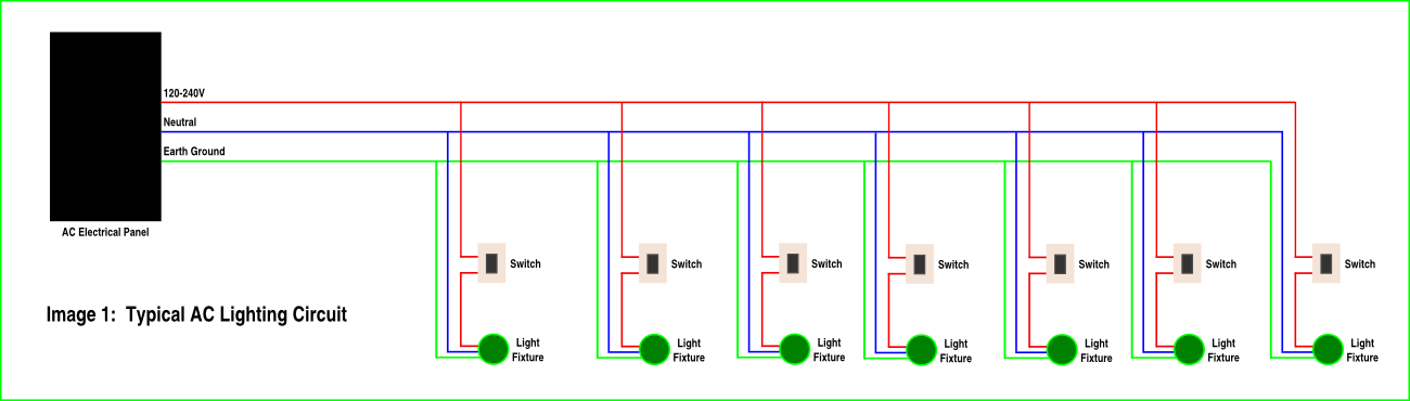
The typical AC lighting circuit (Image 1) consists of 6-8 fixtures sized for an average of 100 Watts keeping the current is limited to 15 amps. Each of the fixtures is wired in parallel and controlled by one or more switches. A three wire cable is used:
- Power is transmitted on one conductor at 120-240V
- Current is returned on the neutral conductor
- The earth ground is used for safety. It is connected to the fixtures so that if a fault occurs the breaker will switch off.
In our DC LED lighting system (Image 2) we use the same conductors in a different way:
- In place of the 120V-240V AC voltage we use a lower DC voltage. It could be between +12V and +48V (ideally below the safety standard).
- We use the neutral conductor for a simple communication bus. This bus can be used to turn lights off and on and control dimming.
- We use the Earth Ground for the return current from the LEDs and the control bus.
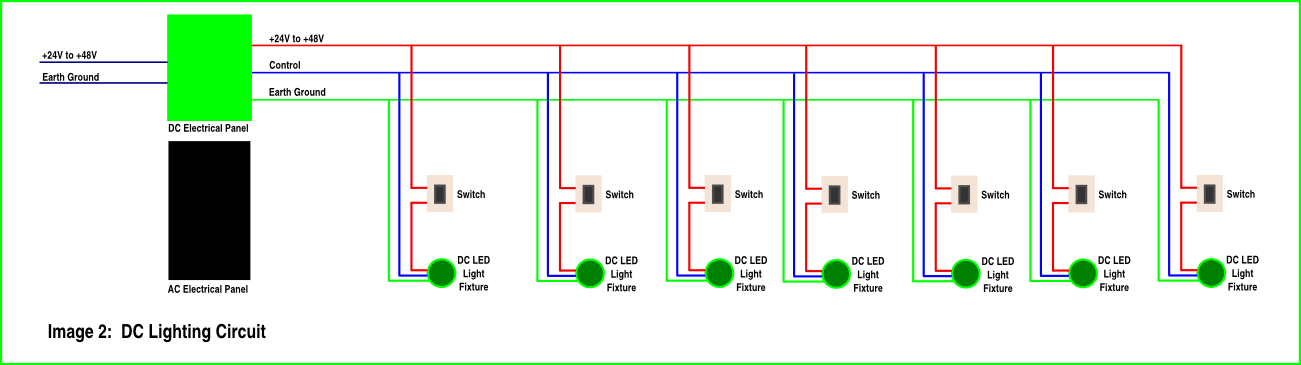
The cables for the lighting circuits would be removed from the AC electrical panel and installed in a new DC electrical panel. It is generally standard practice to have separate circuits for lighting circuits. In most installations the cables can be removed from the existing breaker box and installed in a new DC electrical panel above, below, or to the side of the existing AC panel. This will be the messy part of the retrofit but most of the time it will not be too difficult.
We want to use the power directly from the solar cells or battery. Of course since this is a lighting system it would run off batteries most of the time.
The battery voltage will vary over a wide range but we do not want the brightness of our lights to vary with the voltage so we have implemented the AL8805 buck LED driver in our designs. The AL8805 allows us to vary the brightness of the LEDs using a pulse width modulated (PWM) signal.
The user can set a brightness level and the control microprocessor can vary the PWM signal to match the desired brightness. It can base this on the input voltage from the solar system or an external ambient light sensor in the room.
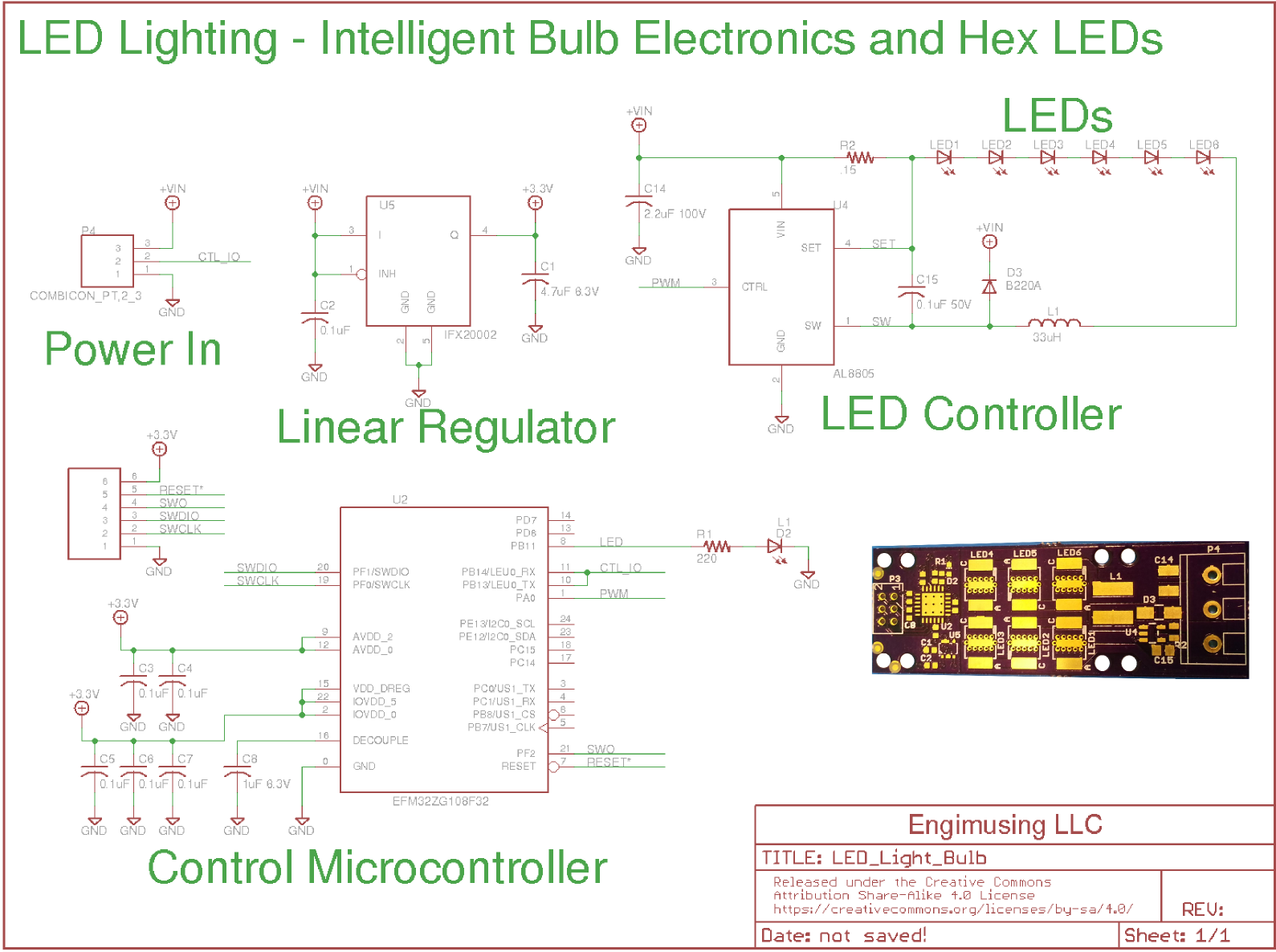
We have developed five different PCBs to experiment with different typologies. The schematic for this particular board contains the significant circuits that are used on all the boards.
We are using a SiLabs low power microcontroller to communicate with the central system and control the LED brightness. The IFX20002 is a linear regulator that converts voltages up to +45V down to +3.3V. We are targeting a 24V system for our tests. We also have a 3 terminal wire to board connector. There are six LEDs on the board and holes for a heat sink to be mounted under the LEDs. This board is 20mm x 58mm (0.78" x 2.28").
This particular board is designed for the lighting topology shown in Image 1 above. The technical challenge with this first topology is the communication via the CTL_IO pin. These wiring systems are likely to be horrible transmission lines with lots of stubs and impedance discontinuities from connectors.
Fortunately we do not have to have a high data rate so we should be able to come up with a reliable protocol that is not impacted by the numerous reflections we expect.
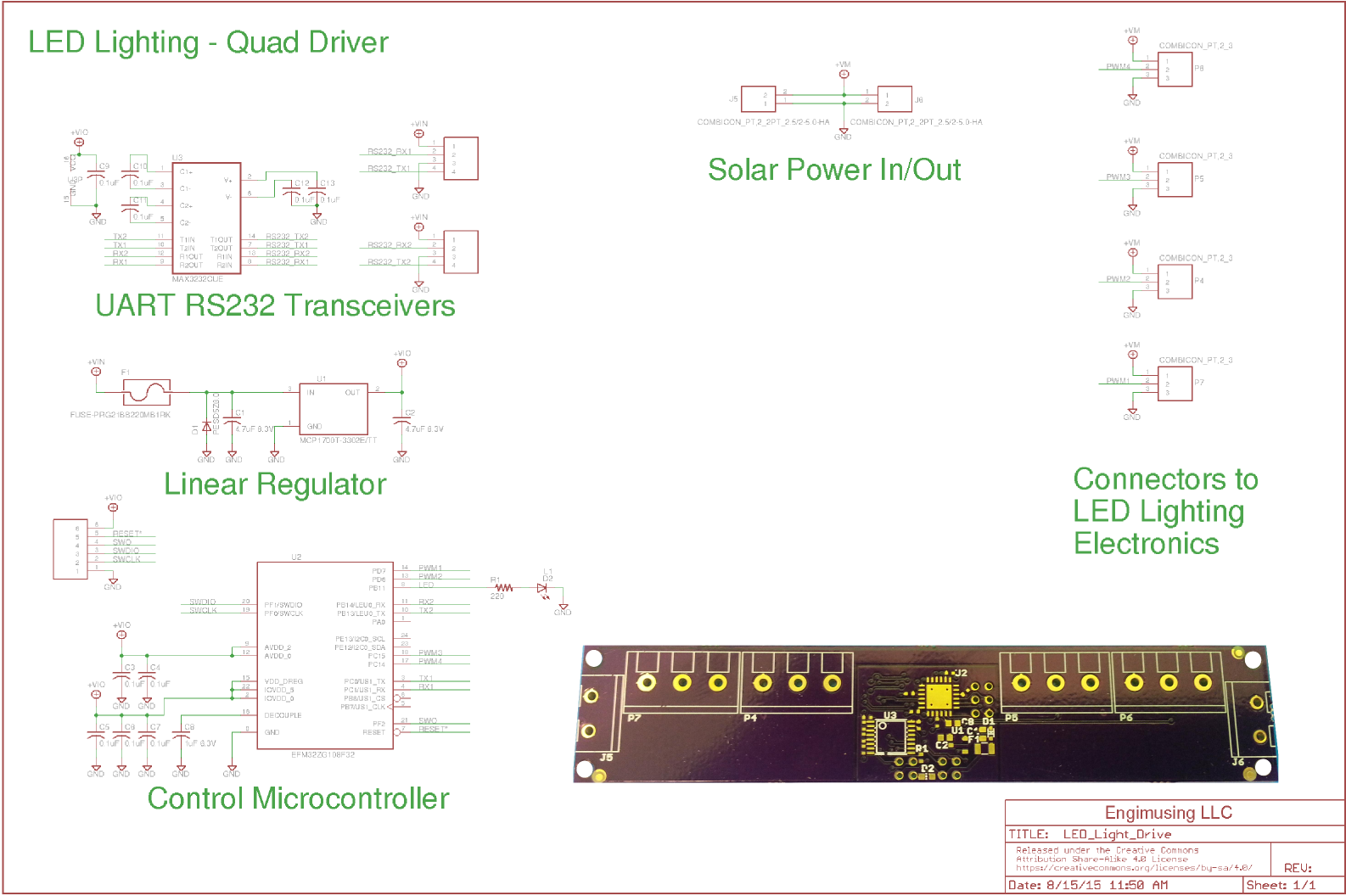
This schematic is for a control board that will reside in the DC electrical panel. It contains a control microprocessor that will communicate with four LED light fixtures. It has dual RS232 channels to communicate with the central home automation server.
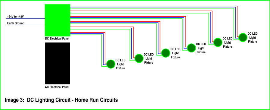
Image 3 shows a different topology in which each light fixture is on a separate circuit. This topology is used in systems where increased central control is desired. I am currently restoring an old house and this is the system I have used.
For an AC system it allows solid state relays to be used for switches and to be controlled using microcontrollers. Using modern low voltage DC LED light fixtures the current requirements are very low. This allows the use of much smaller conductors than traditional AC wiring systems.
In developing countries this could significantly decrease the cost of wiring in a new installation. Not having high voltage AC in the system will also save significant cost.
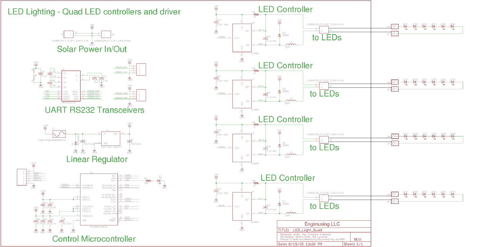
In this topology the LEDs are separated from the AL8805. It is not clear if the AL8805 will be stable in this topology but I want to experiment to see at what distances it will work. I will use this board as an initial breadboard if it doesn't work.
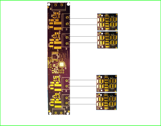
For these tests a four channel controller is designed to control four LED modules.
Summary to Date
This project will prove the efficiency of a DC LED lighting system. It will significantly reduce the size of the solar panel array and the size of the batteries. We will shortly assemble the PCBs and test the different configurations in a laboratory setting. Then we will implement the solutions that work in our home.
Our hardware and firmware are open source. The Eagle files are on GitHub now and when we have working boards we will add more detailed information.