-
Upgrading High Voltage to Source Dual Polarity
09/20/2015 at 08:39 • 0 commentsTo increase the effectiveness of the electrostatic precipitation I upgraded the high voltage DC source to have both positive and negative voltages. This effectively doubles my voltage. I use the negative poll to charge incoming air and the positive poll the absorb the charged particulates. I can place grounding grids in intermediate positions if need be.
I accomplished this by placing another 5 stage Cockroft-Walton multiplier (that has backward facing diodes) to the existing single high voltage transformer. Here is the circuit I followed.
![]()
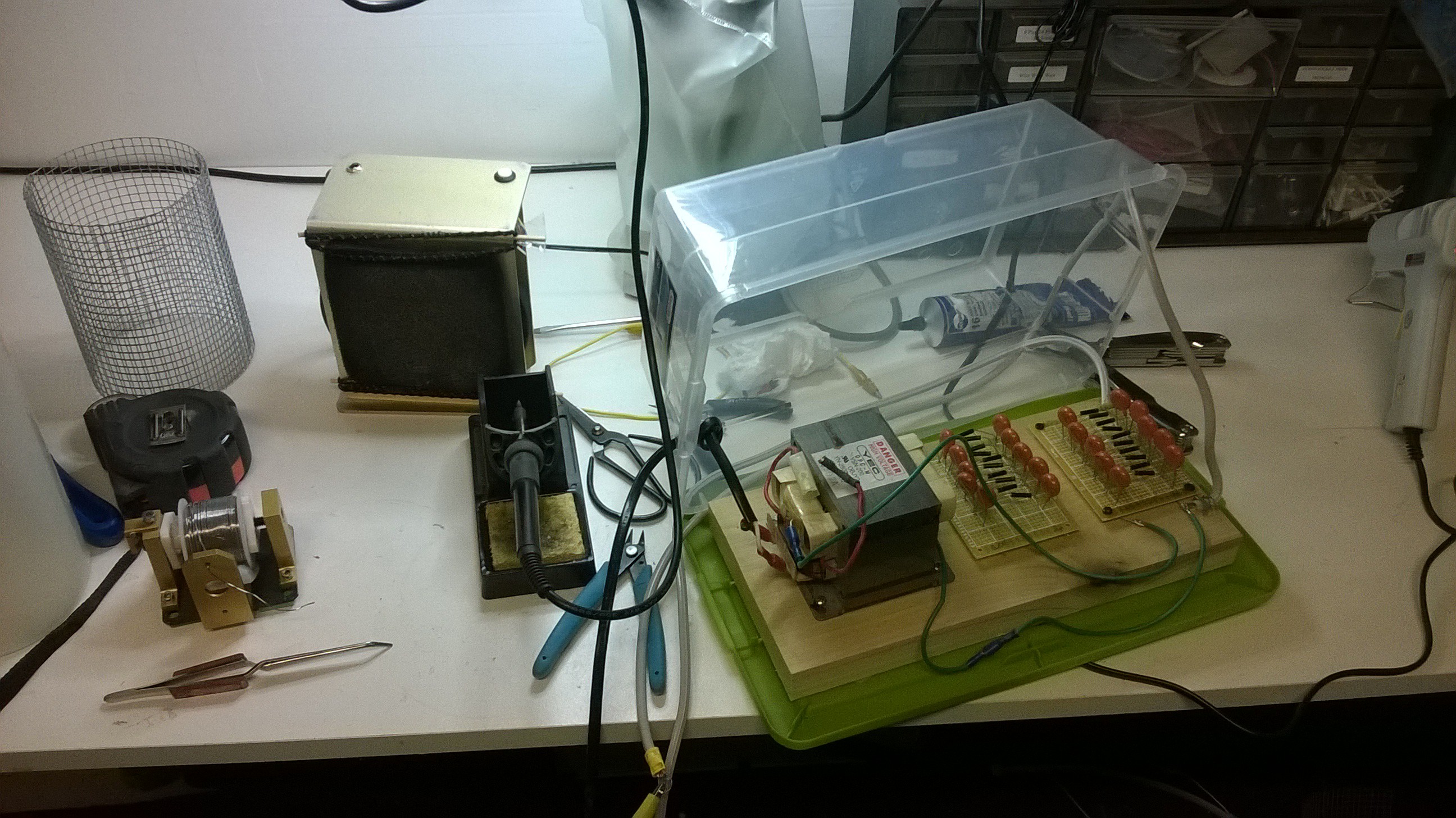
This extra multiplier circuit that provided the negative polarity conveniently fit in the space on the board left between the transformer and the other multiplier.
![]()
![]()
Testing showed that it indeed works. The arcs between the high voltage positive to high voltage negative are about twice as long as those between positive to ground and negative to ground.
-
Building The Smaller Version...
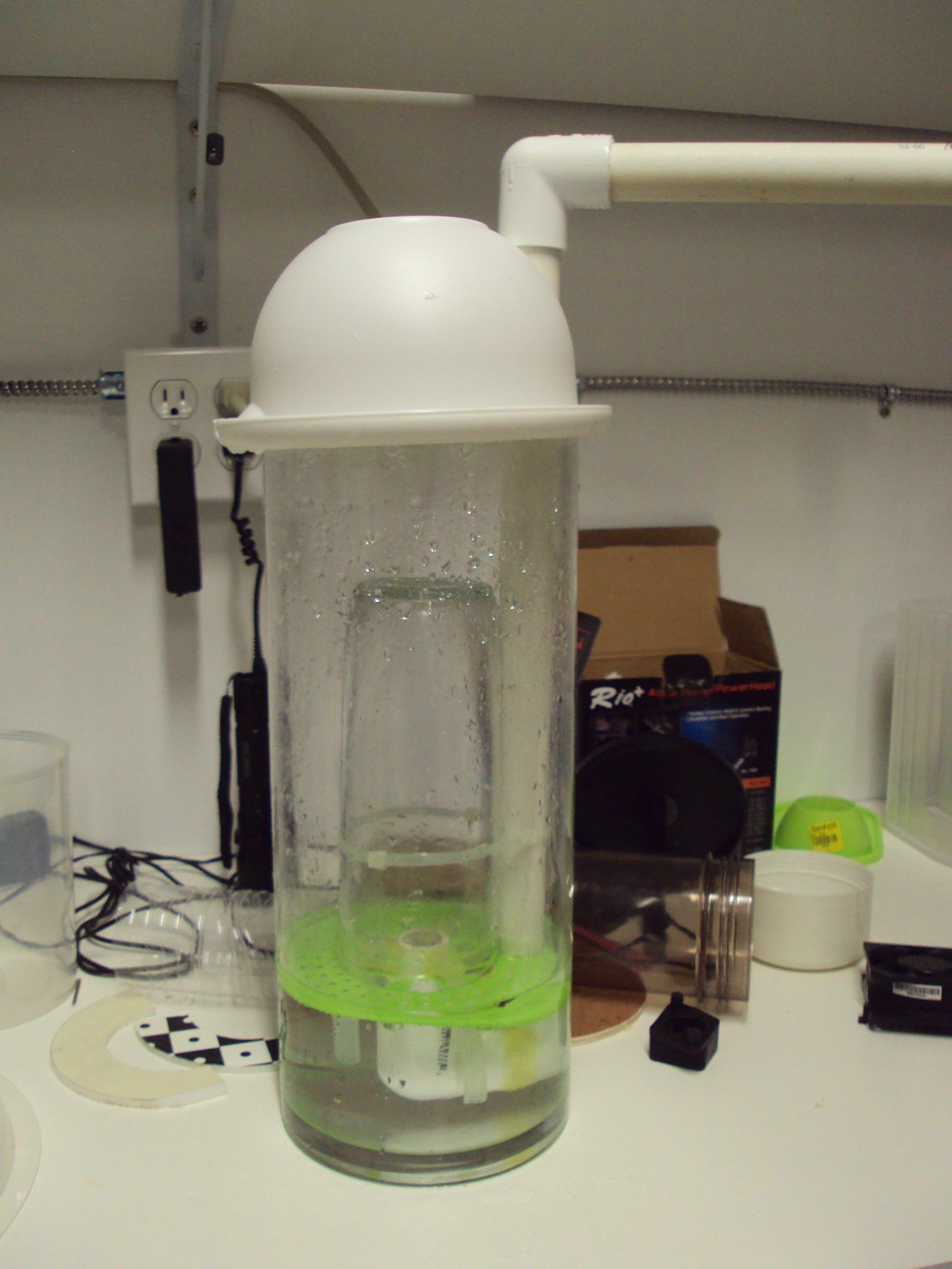
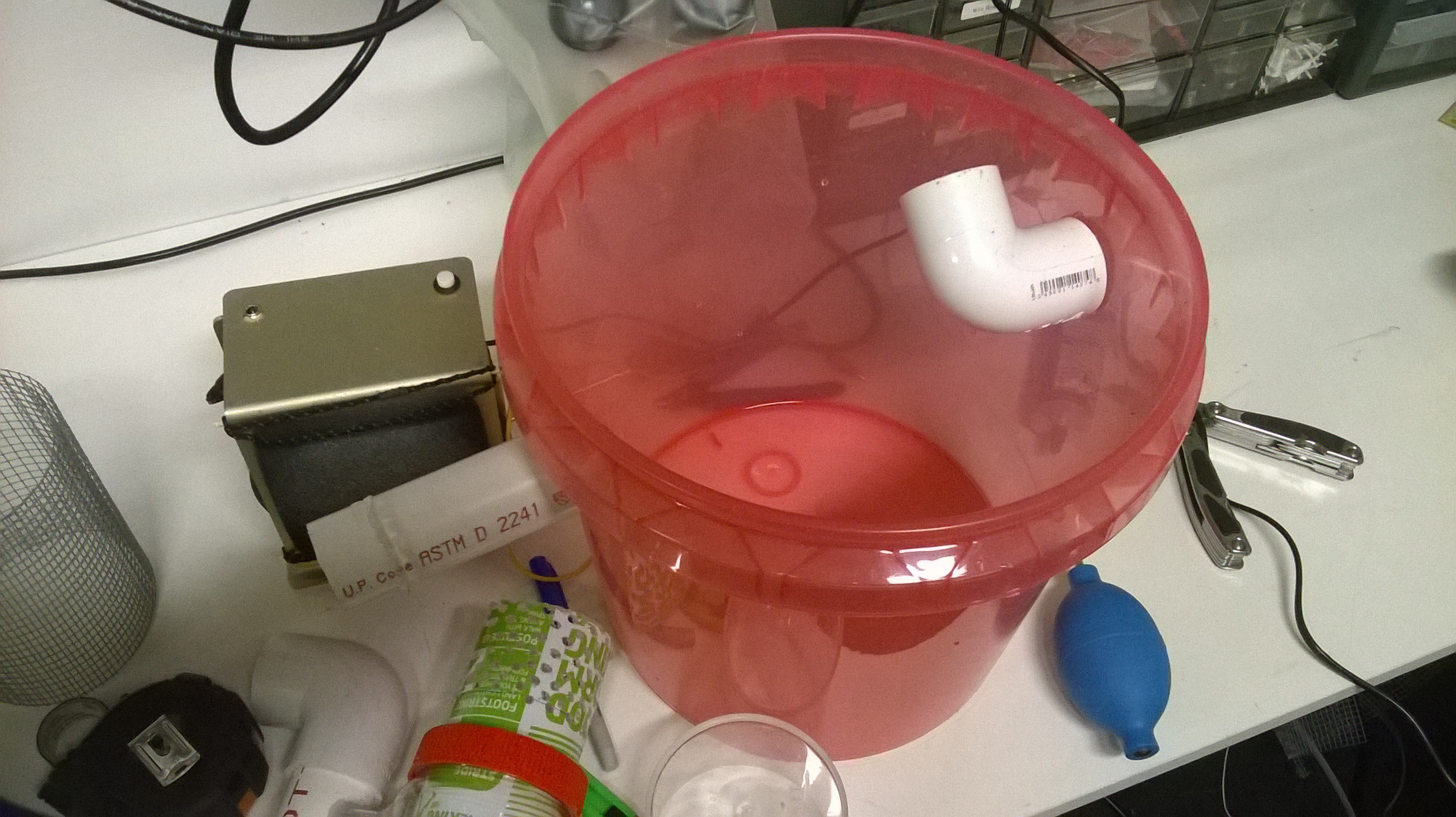
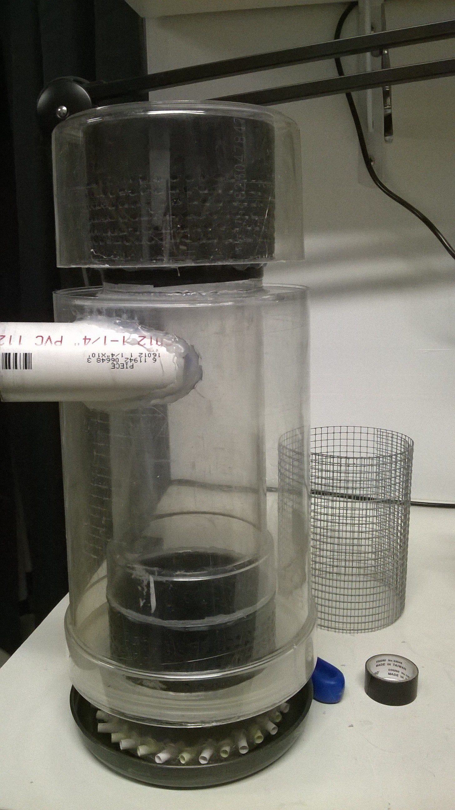
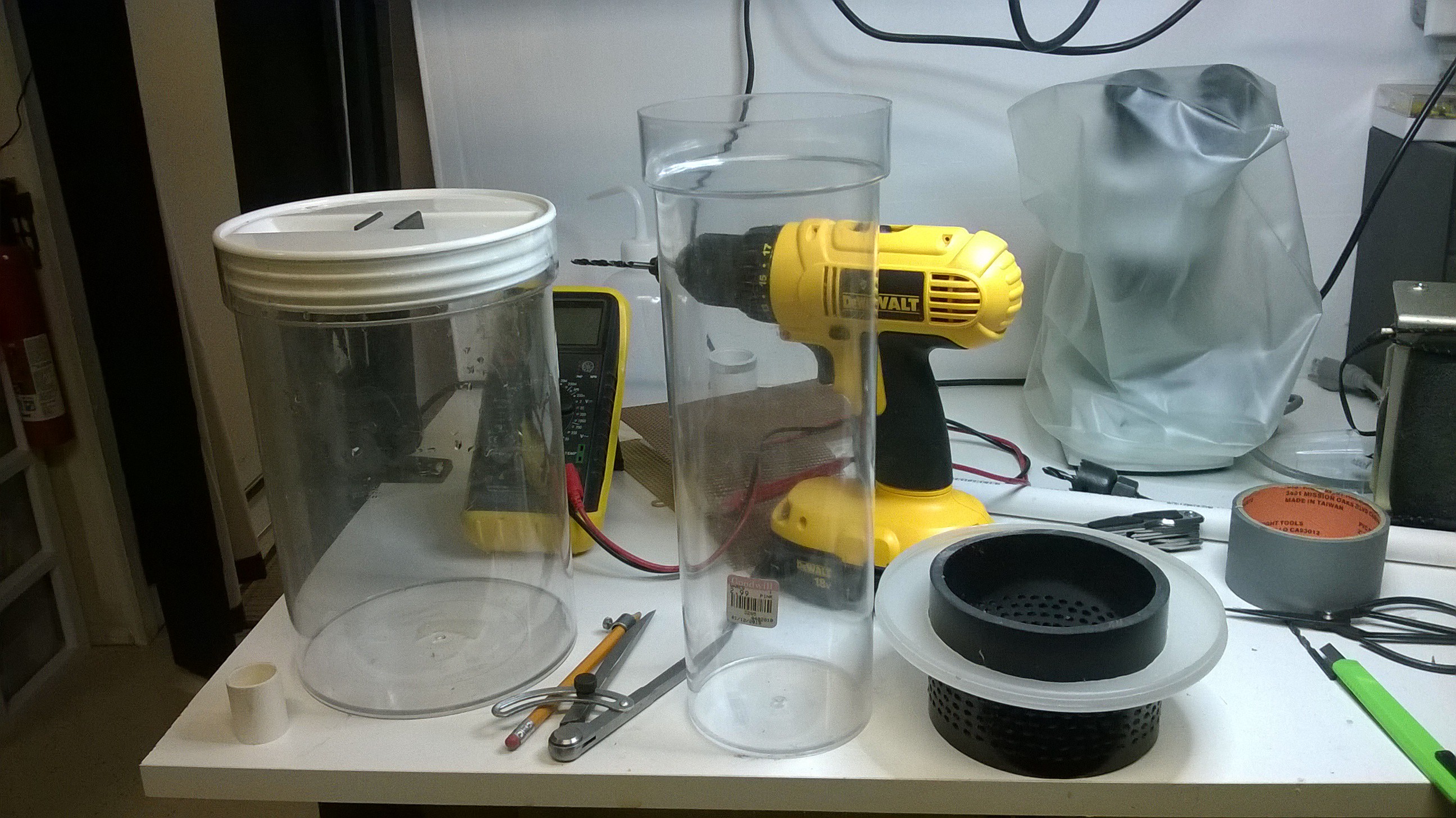
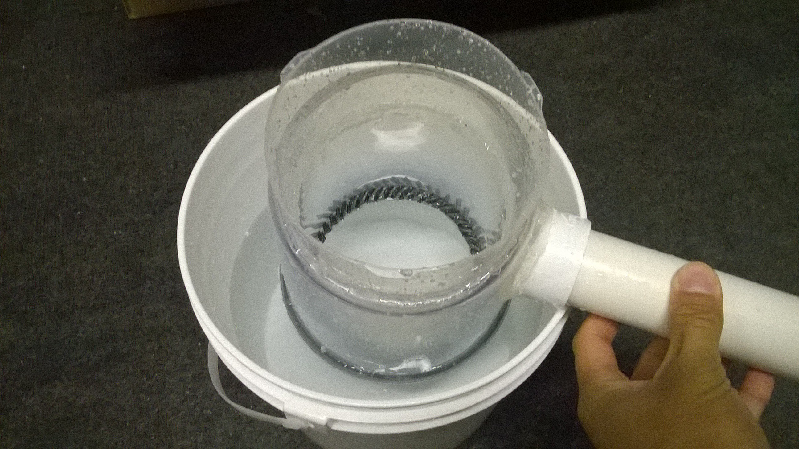
09/20/2015 at 04:44 • 0 commentsOne of my goals was to make the unit smaller. Given my wet scrubber design, it is easy to scale this design down. I used a 3 gallon bucket instead of a 5 gallon and shrank the hollow walled tube to fit inside.
![]()
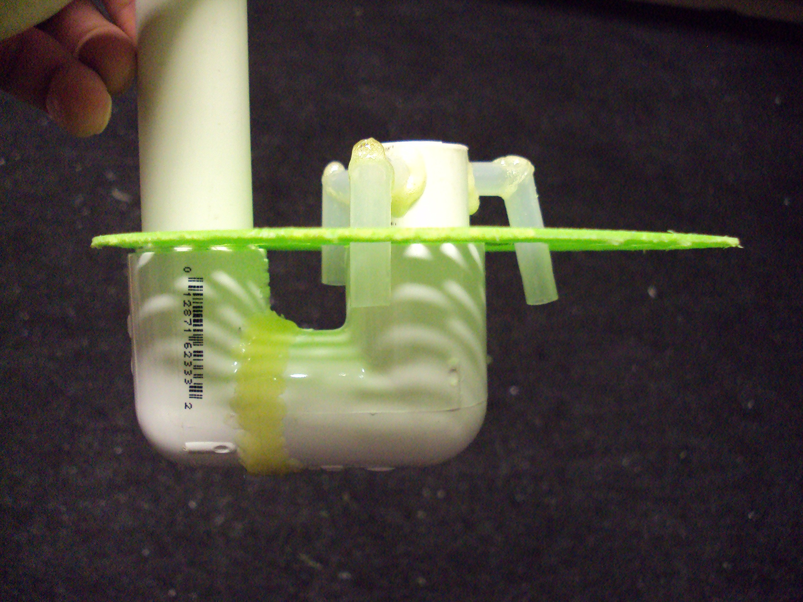
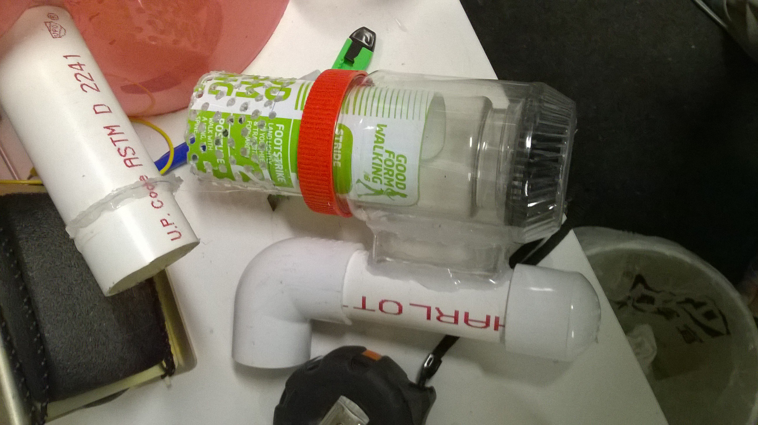
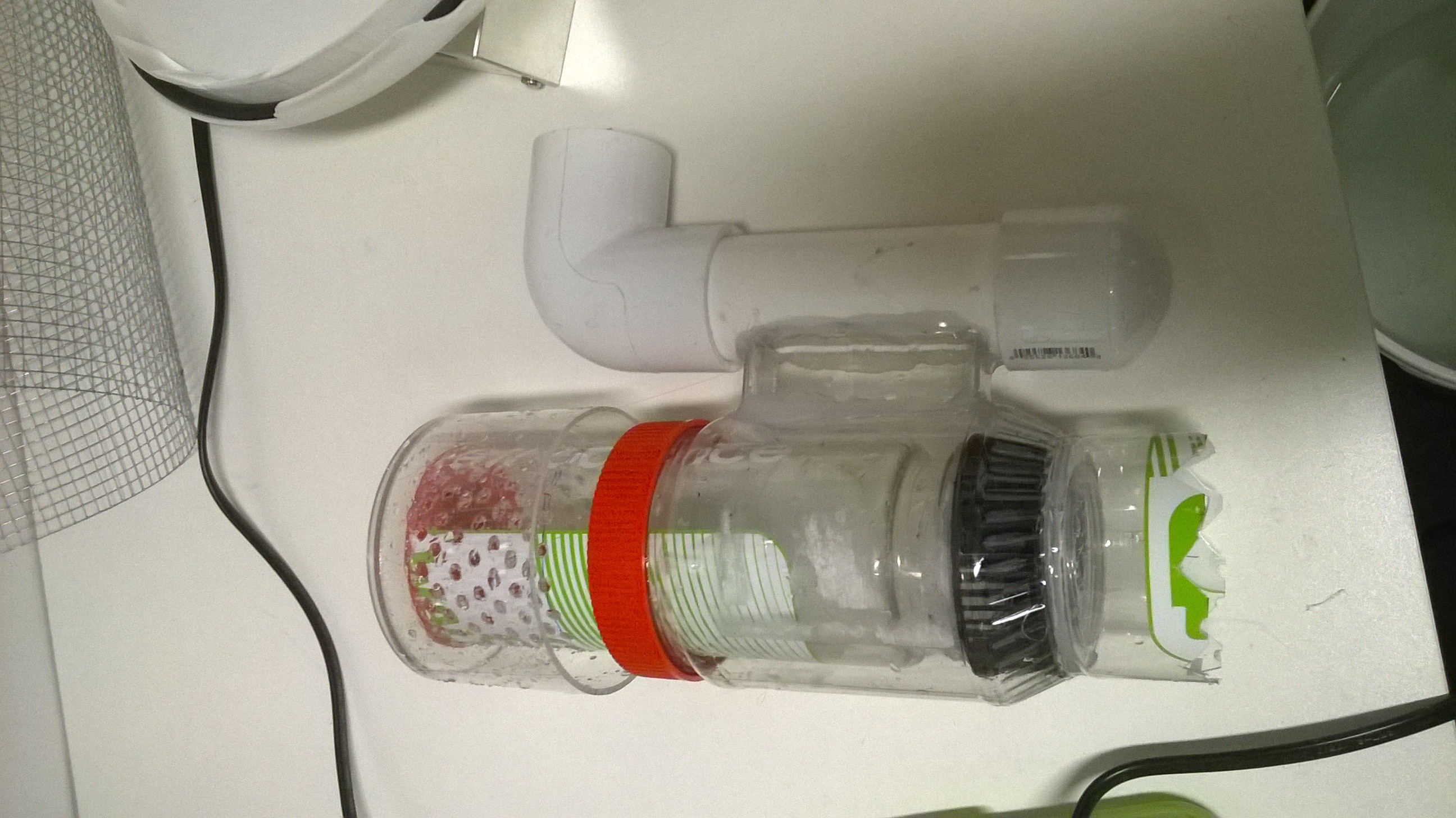
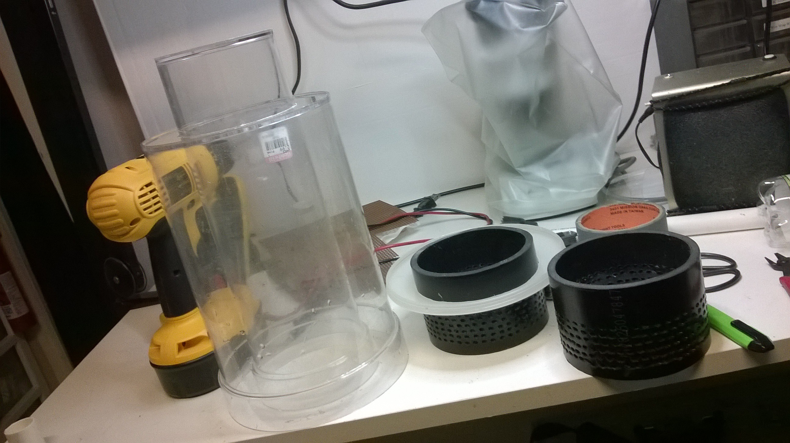
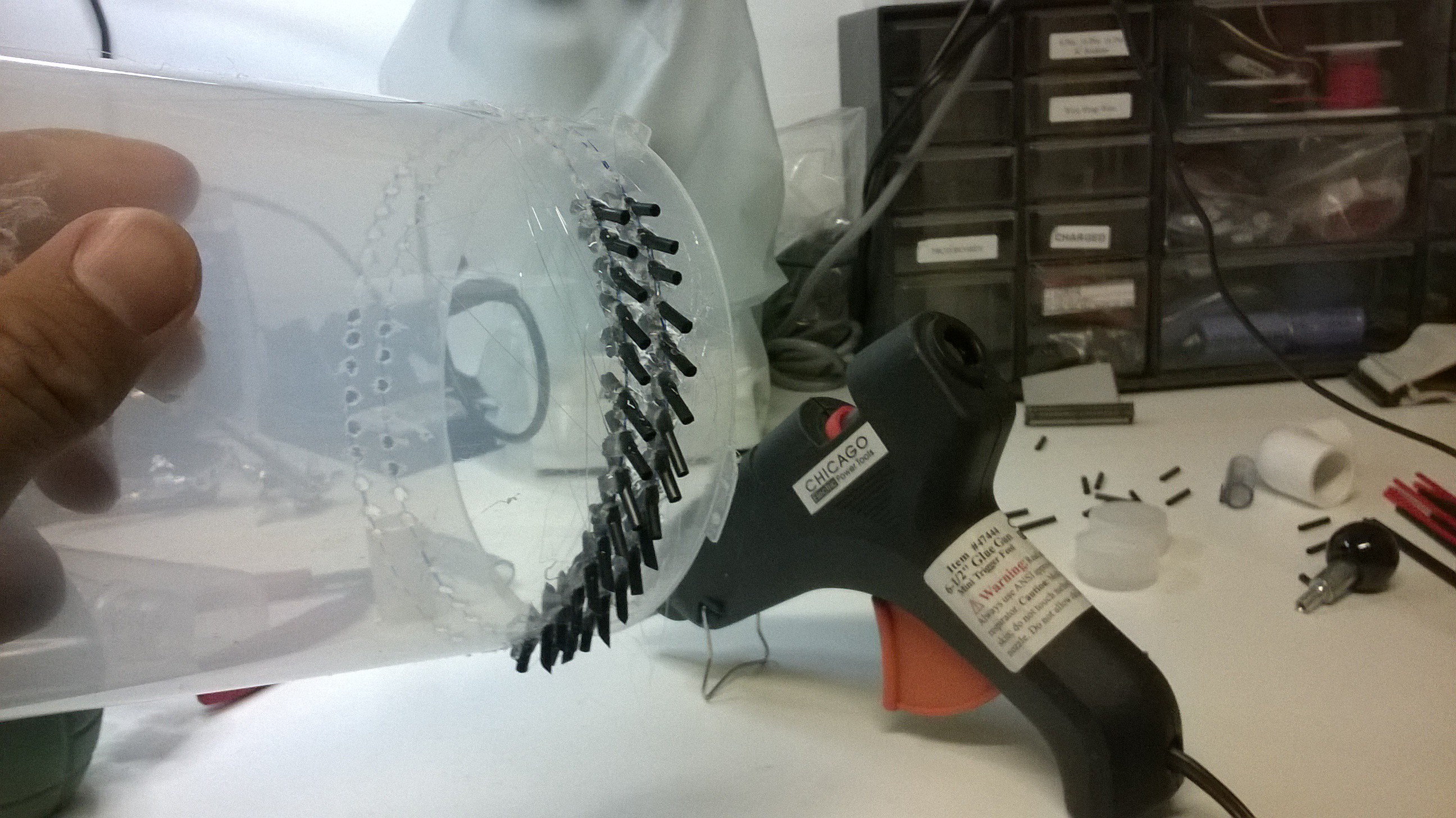
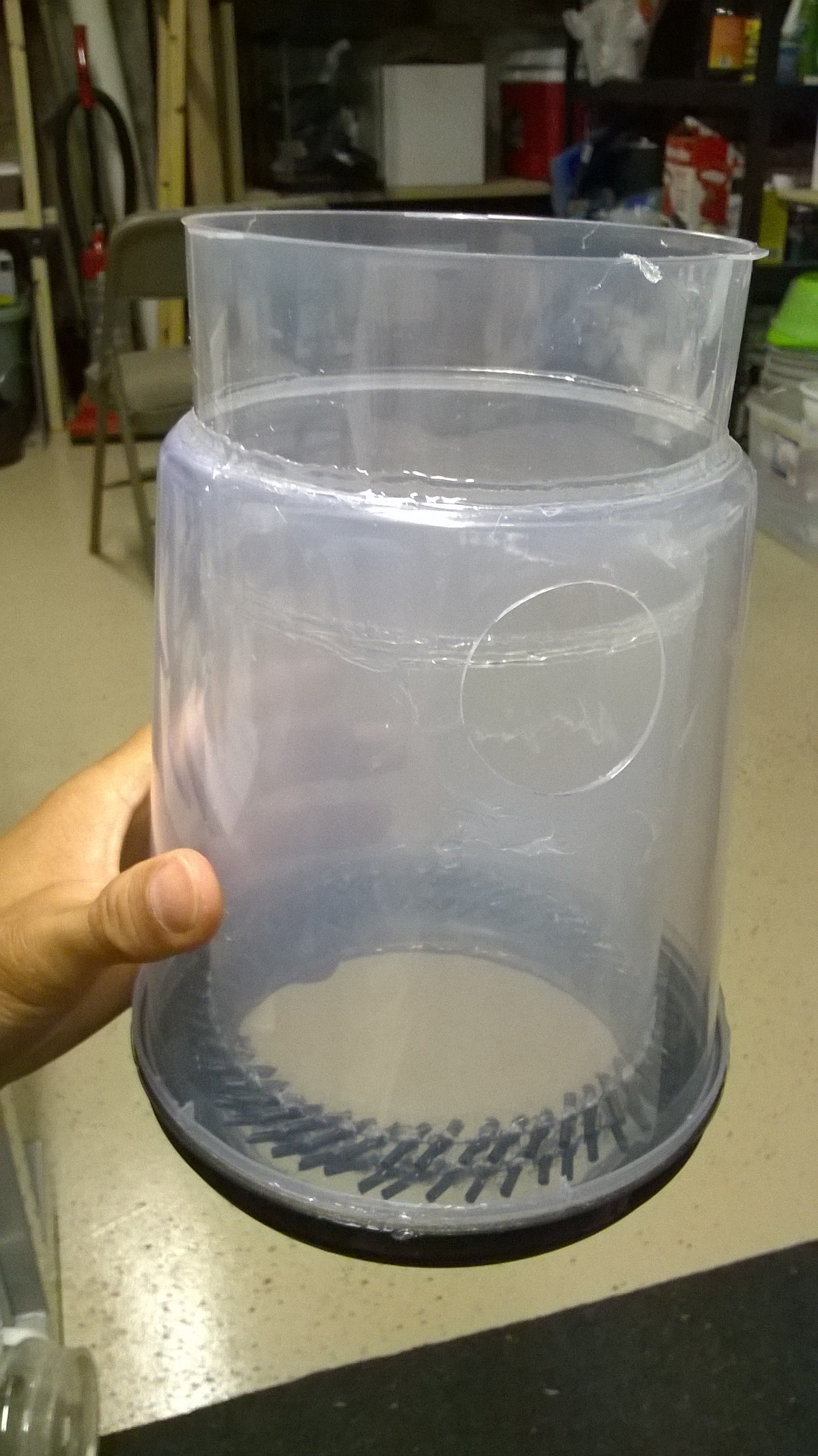
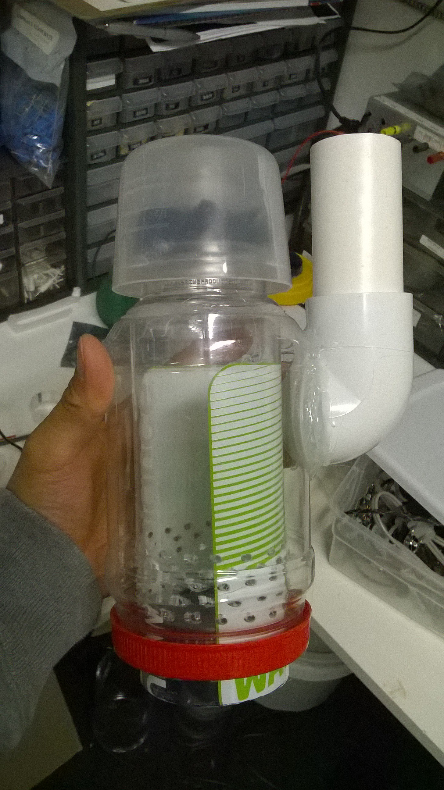
Shrinking the hollow walled tube required using smaller containers. I used a sports bottle that was shoved into a plastic peanut butter jar to create the hollow walled tube. The inward spiraling nozzles was from a computer blower fan that I took apart and glued to the bottom of the sports bottle. I drilled many holes on the top the sports bottle for the exit holes and placed a container on top of this to form the mist eliminator. I piped the air inlet using 1 1/4" PVC pipe and some PVC fittings.
![]()
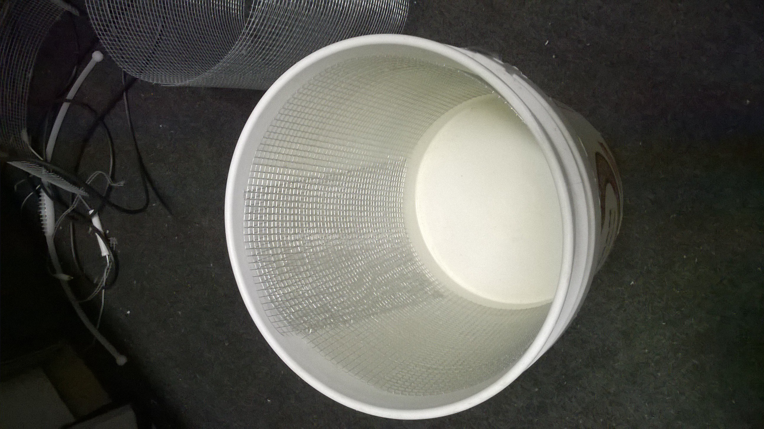
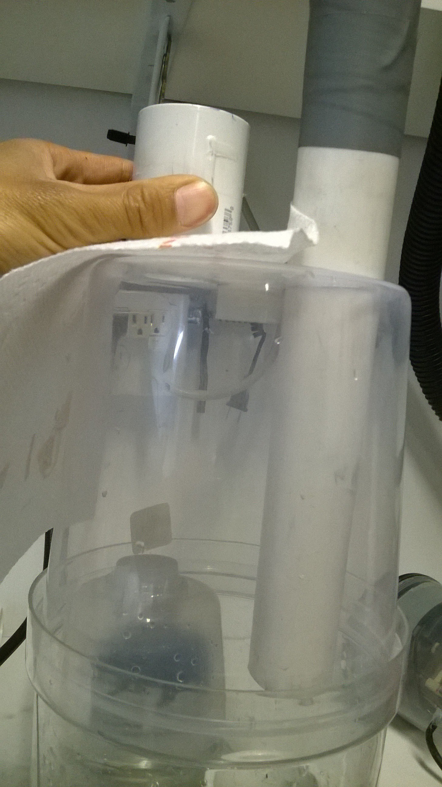
![]() I then drilled a hole in the bucket so the hollow walled tube could be mounted to it.
I then drilled a hole in the bucket so the hollow walled tube could be mounted to it.![]()
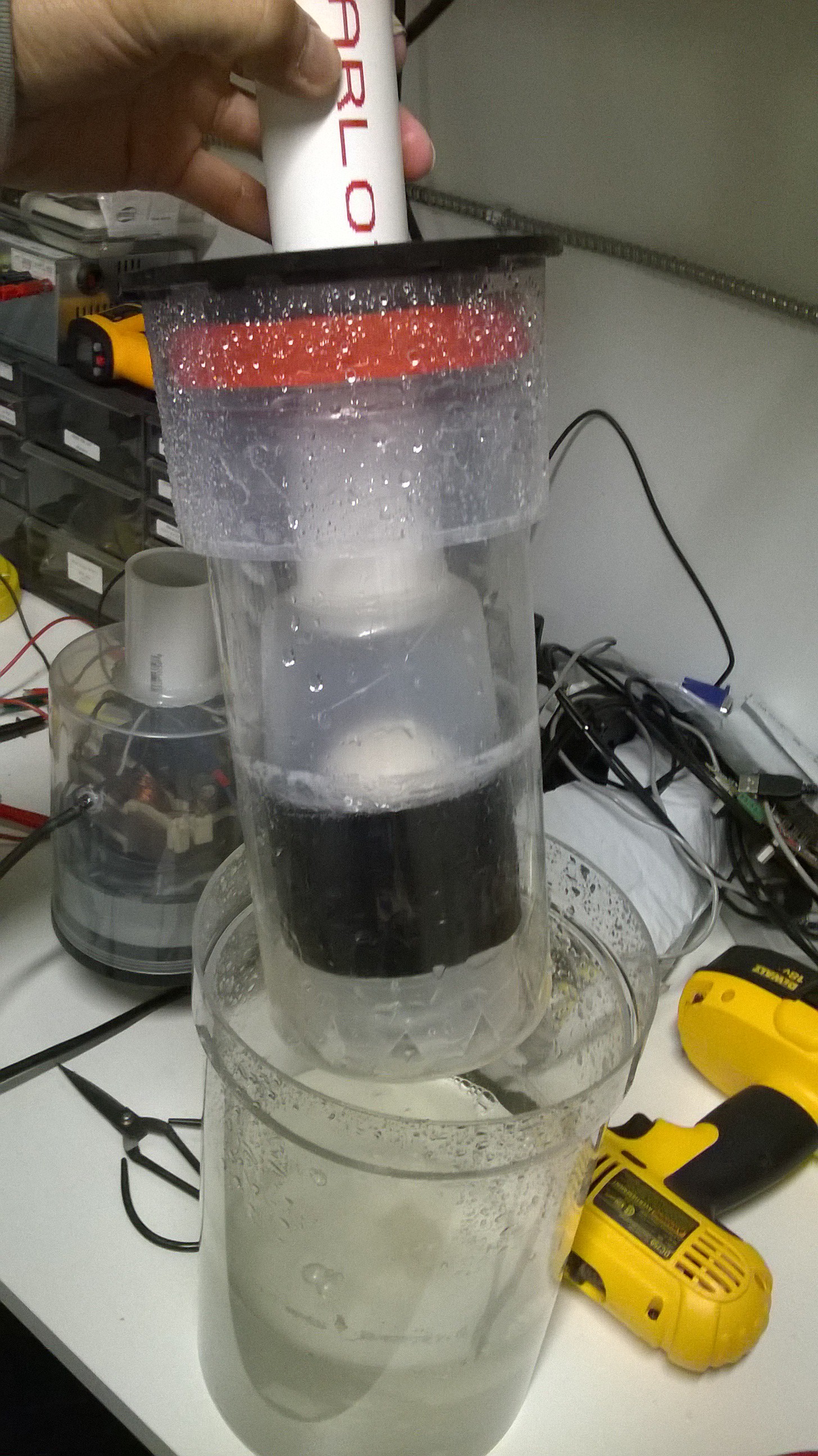
That was it! It worked pretty much the same as the larger version. Here is a test:
-
Trying the Particle Counter
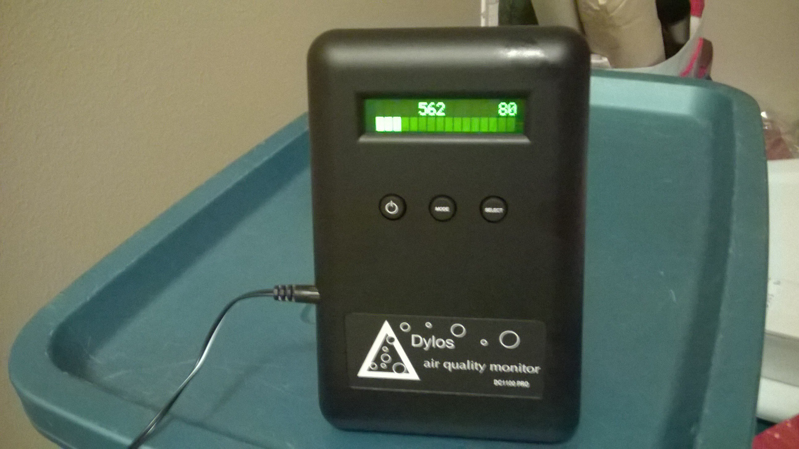
09/19/2015 at 22:33 • 0 commentsAfter my spell with acute bronchitis, I was even more paranoid finding out the performance of my invention. I purchased a particle counter, a Dylos 1100 Pro air quality monitor for a couple hundred dollars. Not cheap. This device is a consumer grade laser based particle counter that can detect particles down to the 0.5um range and 2.5um on the high end. I was hoping to use it to test the performance of my wet scrubber. I thought I would try the device with just the wet scrubber, minus any electrical enhancement stages.
I placed the particle counter in a small room in my house and got some baseline readings.
![]()
The initial reading was about 500 particles/0.01 cubic feet above 0.5um and about 80 particles/0.01 cubic feet above 2.5um.
I placed the wet scrubber in the room and ran it for 30 minutes. When I came back, I was shocked! The counts more than tripled! Ha! This machine produced more particles than filtered??? The readings when to about 1800 and 300 for the 0.5um and 2.5um particles respectively --HA!
It occurred to me that what I was reading was water vapor that was introduced by the wet scrubber's water pulverizing action. I confirmed this by placing an ultrasonic mister near the particle counter and sure enough the particle count skyrocketed. How then do I get an accurate reading of my wet scrubber performance without spending an even larger fortune? Perhaps I can run the wet scrubber and set this number as a baseline count to be subtracted later??? -
Rebuilding the Ionization Stage
09/19/2015 at 22:18 • 0 commentsThe main problem with my last prototype is the high voltage circuit kept shorting out to the liquid below. It was time to fix this problem. I thought to remake the high voltage ionization portion of the device as a completely different stage. I thought to place this portion as a first stage, a pre-charger and then having the wet scrubbing liquid be charged to an opposite polarity. This would involve taking out the existing charge grids from the hollow walled tube in the wet scrubber and placing it in a completely different container and then having air run through that before it hits the wet scrubber.
First order of business was to take apart the old prototype's hollow walled tube. Luckily it didn't completely shatter even though some joints were solvent bonded. I managed to dismantle it, take the charge grid out, and glue it back together with only minor repairs and cracks.
![]()
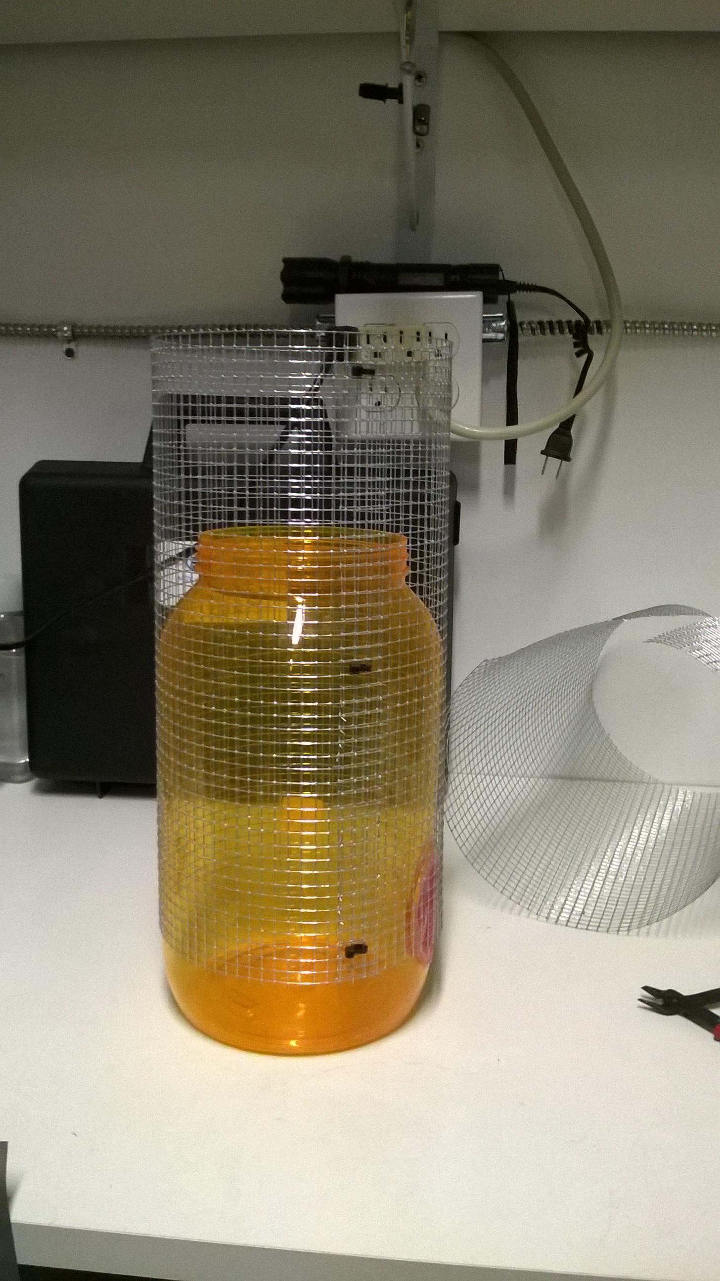
Next was to build the pre charger ionization stage. In order to have the high voltage completely isolated from the wet scrubbing water, I had to use a different container. I was thinking initially to have it as a concentric container either inside or surrounding the 5 gallon bucket that contained the wet scrubber but I did not have such container on hand. Instead I used another 5 gallon bucket and placed the charge grids inside and then simply stack both 5 gallon buckets, ionization and wet scrubber as a one-two stage.
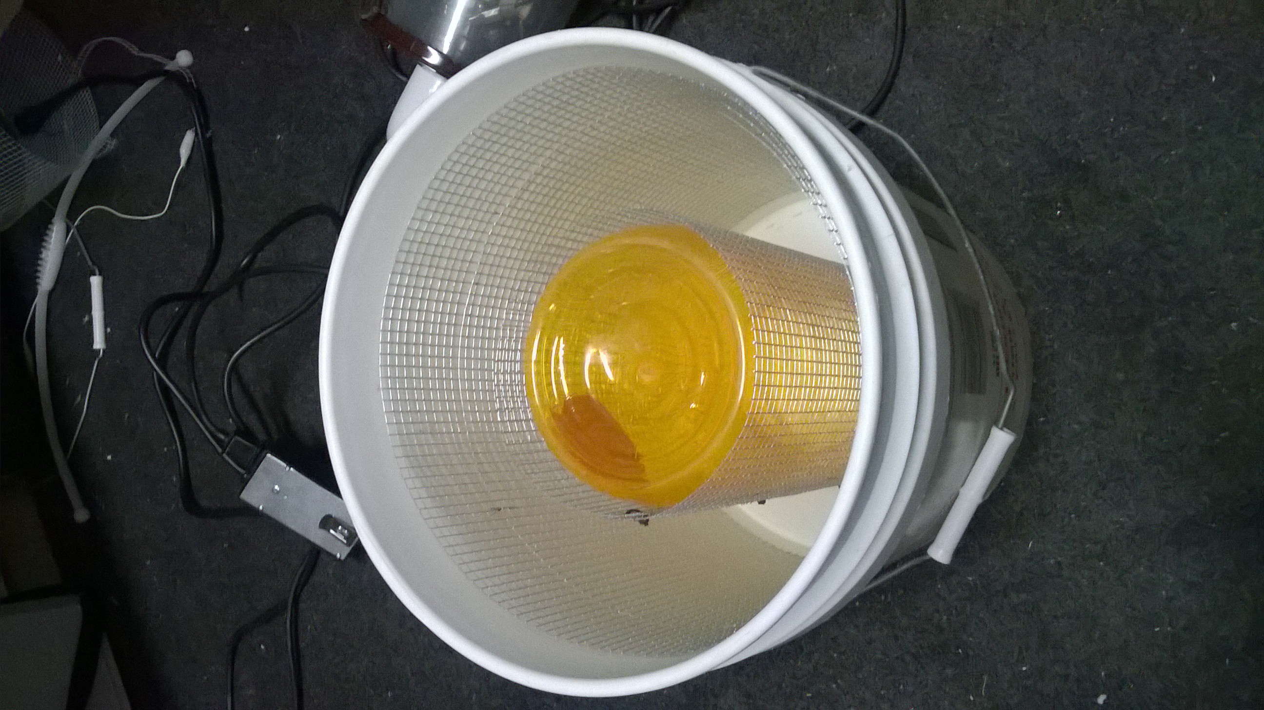
The construction of the ionizer was as follows, a cylindrical metal grid was placed just inside the 5 gallon bucket hugging the wall. An inner cylindrical container is placed in the center of the bucket and contained another cylindrical metal charge grid that hugs the inner container wall. This forms two concentric cylindrical charge grids. The outer grid would be charged to a high voltage and the inner grid would be grounded. Air would enter from the outside of the bucket in an inward spiraling fashion between the outer and inner charge grids thereby charging/ionizing the air. The air would then spiral inward into the inner container and finally exit the bucket and into the next stage (the wet scrubber that has an opposite charge).
![]()
![]()
![]()
I hooked up the charge grids to the high voltage source as a test. It made a very loud and satisfying hiss. What I noticed afterwards was made me stop in my tracks however. Stooping my head over the bucket I had a huge waft of Ozone smell. It dawned on me that this device could produce large amounts of Ozone! This is bad --unacceptable!! If this device produced Ozone, it would actually degrade the air quality not improve it. This left me a little discouraged and left me to go back to the drawing board for a bit.
-
Warning: Acute Bronchitus... Use a Respirator Please!
09/19/2015 at 05:42 • 0 commentsShortly after I made the first submission video, I had come down with a cough. This progressed for a week and I hacked up lots of white phlem. Bad sign. Given that I didn't have any other symptoms like a cold or flu would give, It seems much like acute bronchitis due to inhalation of particulate matter. I should have known better than to not use a respirator during the extreme tests. I lucked out and my lung function returned to normal after one week but it was definitely not a fun experience and now I'm anxious of possible long term effects.
The problem in designing and building a homemade wet scrubber is that there is a high chance it doesn't work the first time or as well as you want it to and in this case it gave a false sense of security when sucking up smoke and other shop dusts. My wet scrubber showed results that it could filter down to 2um particle range showing penetration for particles of 1um and below. Sub-micron particulates, namely smoke, was definitely penetrating the filter and I'm sure super fine shop dust got through. I experienced it in a terrible way, unfiltered. I'm praying the dust I inhaled isn't silicon or something else toxic. Also no wet scrubber alone will scrub out VOC's (which is a gas, not a particle) less that VOC is liquid soluble and any combustion product will contain a cocktail of harmful VOC's.
So if you the reader plans to build one of these please please please always use a respirator when testing until you can determine for sure the scrubber is working properly and also do not use the device beyond its cabability. Don't let this device give a false sense of security like I did. Consider yourself warned.
-
My 2min Project Submission Video & Testing Results
08/16/2015 at 10:15 • 0 commentsAbove is my submission video...
First Tests of My Latest Prototype
I tested my latest prototype first by filling it with water and turning on the electricity and the vacuum motor. ZAAAP!! the high voltage electricity applied to the cylindrical charging grids kept shorting out to the water that the wet scrubber was submerged in and the lights kept flickering in my lab. This did not bode well.... I had to go plan B and add a wired brush inside the inlet pipe to perform the charging and disconnect the cylindrical charge grids that were inside the hollow walled tube of the wet scrubber. I was a little sad as plan B does not allow the incoming air much time to be ionized before reaching the wet scrubber nozzles.
Moving onwards I turned on the electricity with plan B using the inlet pipe charging brush. It made a nice satisfying HISS! and I could hear the air being ionized with an electric wind. At least plan B works, even if it is only a tiny bit.
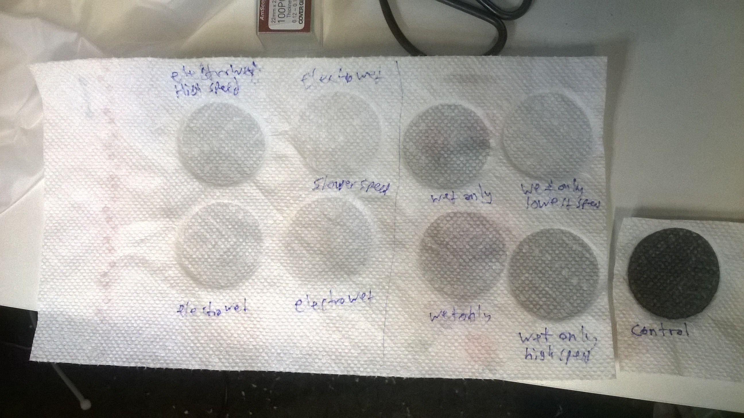
I went on to test my prototype by piping in activated carbon dust into the inlet and placing a paper towel at the exit port to see what got through. I first created a control sample by bypassing my entire wet scrubber filtration and sucking the carbon dust directly into a paper towel. This made a very black sample.
I then went ahead and tested the wet scrubber without electrical augmentation using the carbon dust and paper towel to sample. For the final test, I turned on both electrical augmentation and wet scrubber.
![]()
The data showed that the wet scrubber filtered most of the large particulates, and the electrical augmentation had only a slight effect in capturing more particulates. The samples were not pure white however which was disappointing. The negligible performance of the electrical augmentation was expected to some degree as there was barely any time for the incoming air to ionize traveling at high velocities. Had the original design not shorted perhaps, the cyclonic spiral motion would give a longer path and more time for the air to properly charge. Furthermore, part of the disappointing performance may have resulted from the fact that putting a paper towel at the exit port places a huge air resistance to the system causing the wet scrubber to not work as efficiently so I may have botched my results by reducing the air flow.
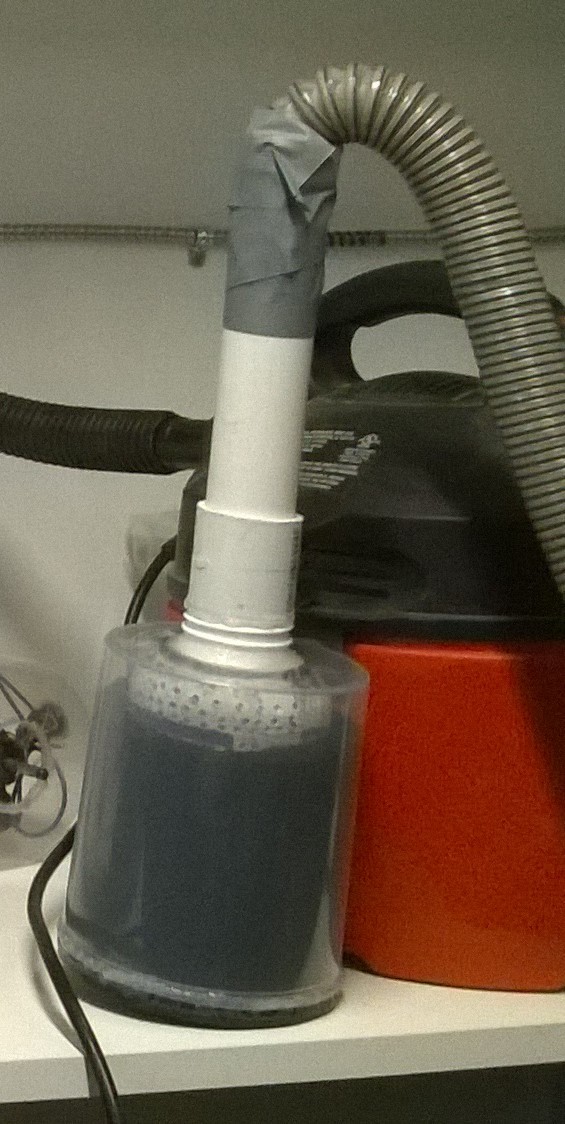
I performed multiple tests at different speeds. Strangely however, the system seemed to favor lower speeds as the samples for lower speeds seem whiter. That is counter intuitive as higher wet scrubber velocities tend to mean better performance. This may mean that the method of how I was piping in the carbon dust into the inlet port was flawed. I simply stuck a pipe into a container containing loose carbon pellets with cloth barrier preventing the large pellets getting sucked in so only the carbon powder would get through. This probably caused greater air resistance than the paper towel and therefore slower speeds simply sucked in less carbon dust than higher speeds. A picture of the jury rigged canister of loose carbon is shown here below.
![]()
I now know where to focus my efforts next time and that is to get the electrostatic booster stage working properly without plan B. There does exist a trade off condition that higher air flow improves the wet scrubber performance due to higher impaction velocities but lower air flow improves the electrostatic charging as it gives more time to ionize particles. It will be quite a challenge to balance these two factors in my next design. I also must improve upon how I am testing the system so my data is not as confusing and counter intuitive.
-
Iteration 3: Combining High Voltage to the Wet Scrubber
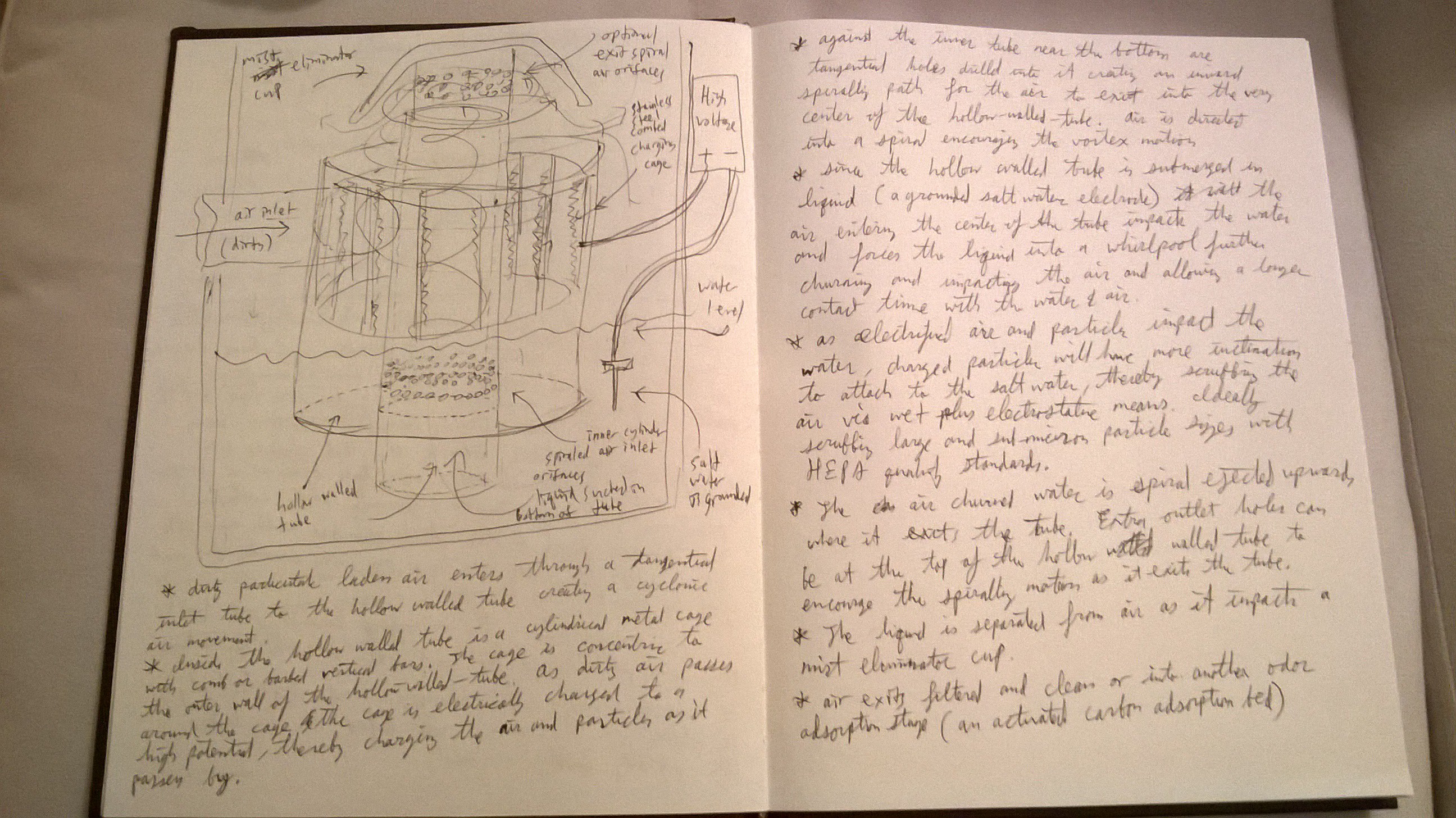
08/16/2015 at 08:19 • 0 commentsHERE IS MY SYSTEM DESIGN DOCUMENT:
![System Design Document]()
This past week has been busy building my latest prototype version for the Hackaday competition. I had abandoned the constraint of keeping the prototypes to a counter top form factor simply for ease of construction. I can later scale down the design once I get a prototype that works to my level of satisfaction.
I have tested that the high voltage circuit works reliably and can suck smoke out of the air in an enclosed chamber. Now is the time to integrate high voltage with churning water.... Sooo amazingly dangerous!
The high voltage circuit was dangerous enough by itself. To add to the danger, the capacitors in the cockcroft-walton multiplier kept its charge even after turning the power off. After each run, I would short out each capacitor with a long stick that had aluminum foil on the end just so I can rearrange the terminals.
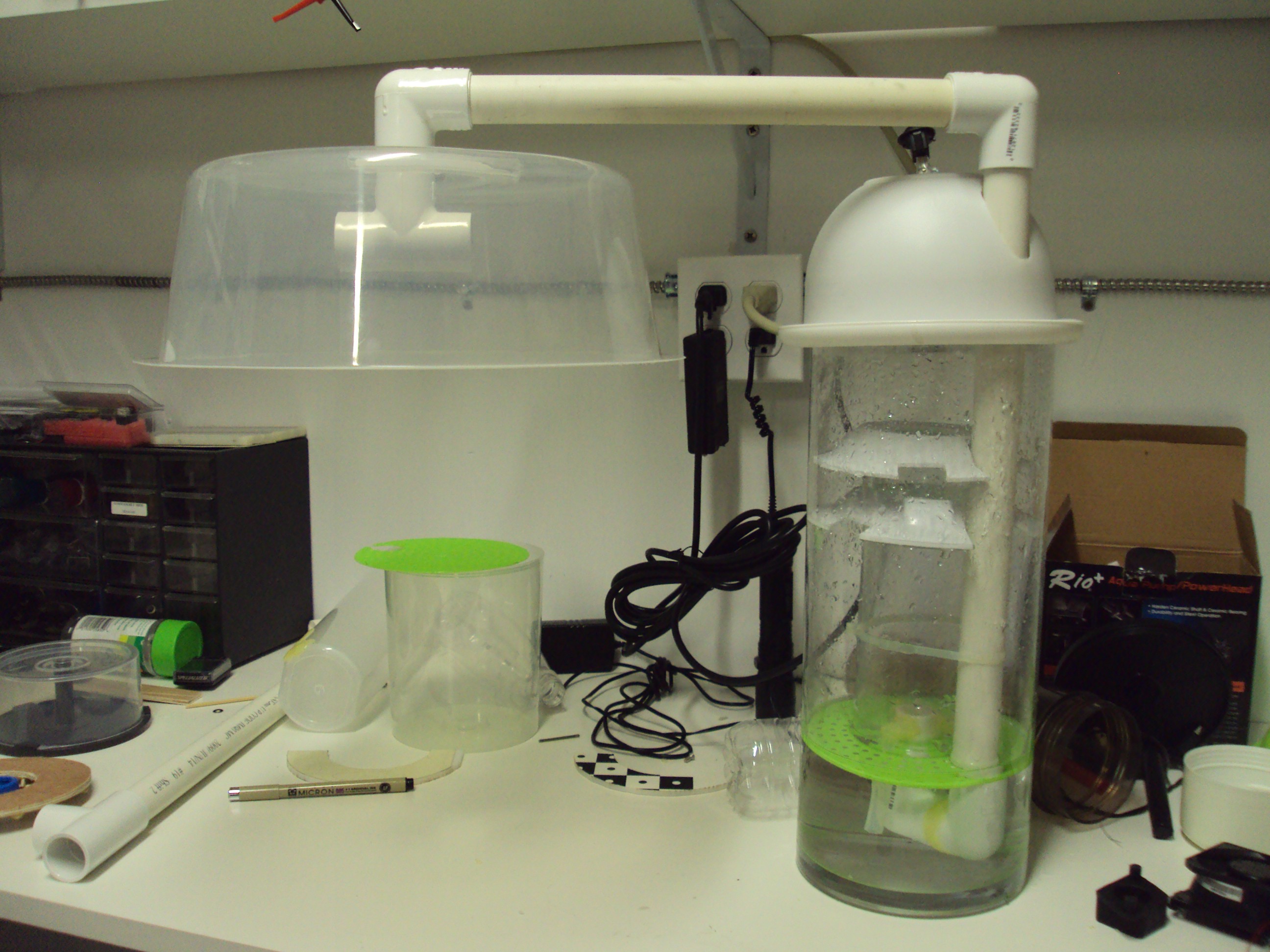
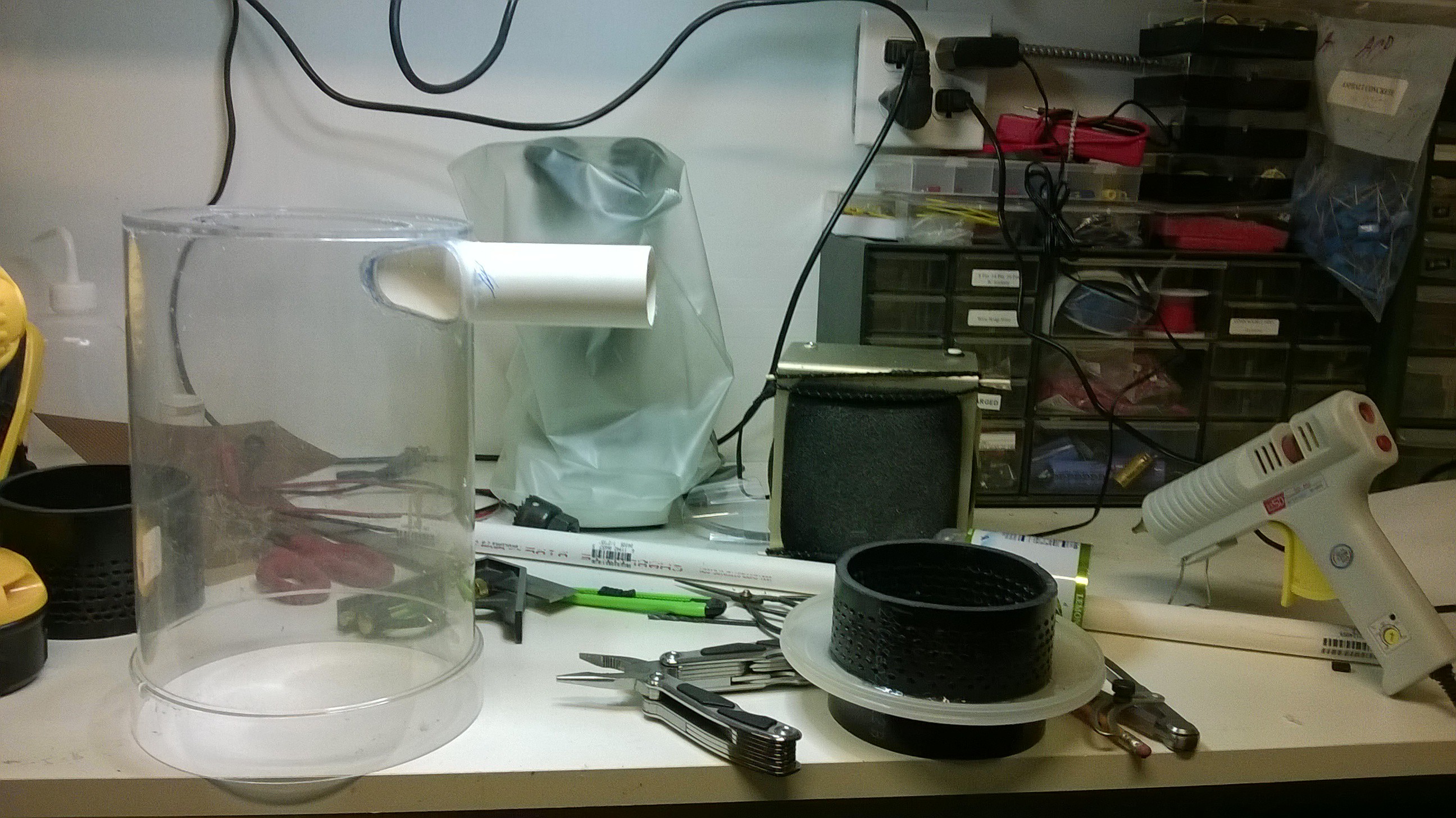
I wanted to make this prototype a little more cleaner so I used larger containers (all my material being sourced from Goodwill thrift store). I had a large clear cylindrical food container and a narrower taller one that I would insert inside. This creates the hollow walled tube.
![]()
![]()
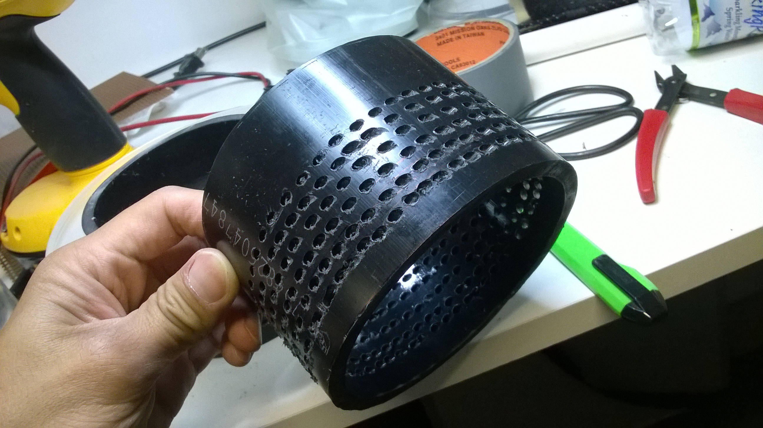
To create the spiral nozzles, took 4" slices of schedule 40 ABS pipe and drilled numerous holes that angle inward tangentially to create an inward spiral. This is much faster than drilling holes and gluing inlet pipes to create the spiraling nozzles. During operation, the entire assembly is placed in scrubbing liquid (water) with the liquid level being above the inward spiraling nozzles. Note that there must be sufficient number of holes so there is not a great air resistance placed on the blower motor.
![]()
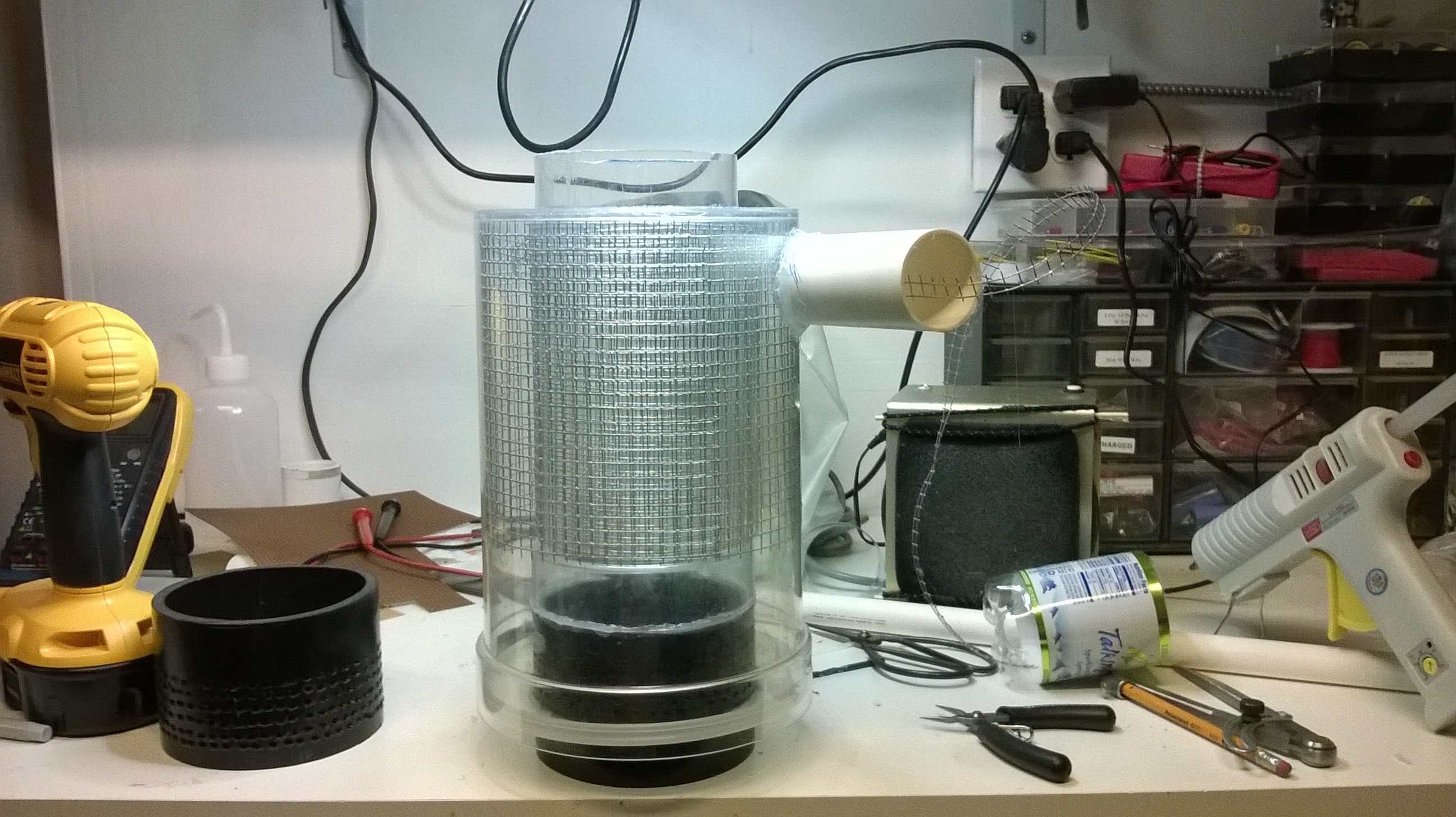
I planned to insert the ionizing grid inside the hollow walled section of the tube. To make the grid I took some 1/4" in fencing grid from Home Depot and cut it into two cylindrical sections. One grid section would hug the outer wall of the hollow walled tube and the other charging grid section would hug the inner wall of the hollow walled tube. This allows a cylindrical path for the air to be ionized before it enters the inward spiraling nozzles. To give the incoming particulate laden air more time to ionize, I piped the inlet nozzle tangentially to the inside of the hollow walled tube causing the incoming air to follow a longer cyclonic path before it enters the spiraling nozzles.
![]()
![]() For the mist eliminator section, I took another slice of the ABS pipe and drilled a bunch of inward spiraling holes into it and flipped it over so it spirals outwards compared to the nozzles at the bottom. These holes help continue the spiraling motion of the misty air in the inner tube until it exists in an outward spiraling fashion.
For the mist eliminator section, I took another slice of the ABS pipe and drilled a bunch of inward spiraling holes into it and flipped it over so it spirals outwards compared to the nozzles at the bottom. These holes help continue the spiraling motion of the misty air in the inner tube until it exists in an outward spiraling fashion. ![top view of wet scrubber looking into the hollow walled tube]() A bowl like container is placed on top of the inner tube sealing it forcing the misty air to exit the outward spiraling nozzles. As the misty air exist the outward spiraling nozzles at the top of the hollow walled tube, it will crash into the bowl that is placed over the nozzles, thereby separating the mist from the air. Note the number of holes on the outward spiraling nozzles must be equal to or greater than that of then inward spiraling nozzles so to let the misty air exit out the top and not escape out the bottom of the hollow walled tube and bypass the scrubbing action.
A bowl like container is placed on top of the inner tube sealing it forcing the misty air to exit the outward spiraling nozzles. As the misty air exist the outward spiraling nozzles at the top of the hollow walled tube, it will crash into the bowl that is placed over the nozzles, thereby separating the mist from the air. Note the number of holes on the outward spiraling nozzles must be equal to or greater than that of then inward spiraling nozzles so to let the misty air exit out the top and not escape out the bottom of the hollow walled tube and bypass the scrubbing action.![]() The charge grids had a wire that ran through the air inlet pipe and terminated at a screw on a PVC "T" joint. I made it this way so the high voltage circuit could easily be attached to the terminal from the outside.
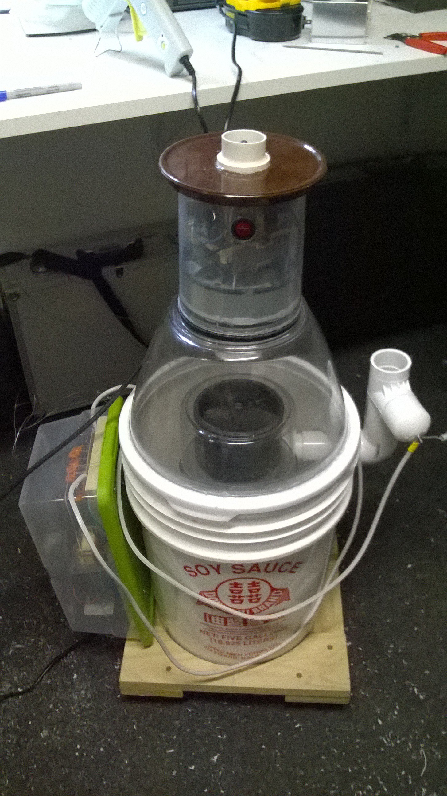
The charge grids had a wire that ran through the air inlet pipe and terminated at a screw on a PVC "T" joint. I made it this way so the high voltage circuit could easily be attached to the terminal from the outside.To submerge the entire assembly I used a 5 gallon bucket my Dad got for me for free at the Safeway China Express / Deli. Yes, it is a soy sauce bucket, it adds a kick of special flavor to the air... I drilled a hole into it centering the scrubber unit in the center of the bucket. I then used epoxy puddy to secure the port I created.
The entire assembly protruded from the bucket so I needed a dome type lid. A salad spinner from Good Will was perfect for this and since it was clear I could easily see what was going on inside.
![]()
For this larger iteration prototype, I used a larger vacuum motor to provide greater air flow. I took apart a vacuum cleaner and placed the vacuum motor in a CD case so I can easily attach PVC pipe fittings to the input and output. Debating whether to put the motor and high voltage circuit in another bucket below the 5 gallon bucket, I went ahead and kept it to a one 5 gallon bucket design and placed the vacuum motor on top of everything.
![]()
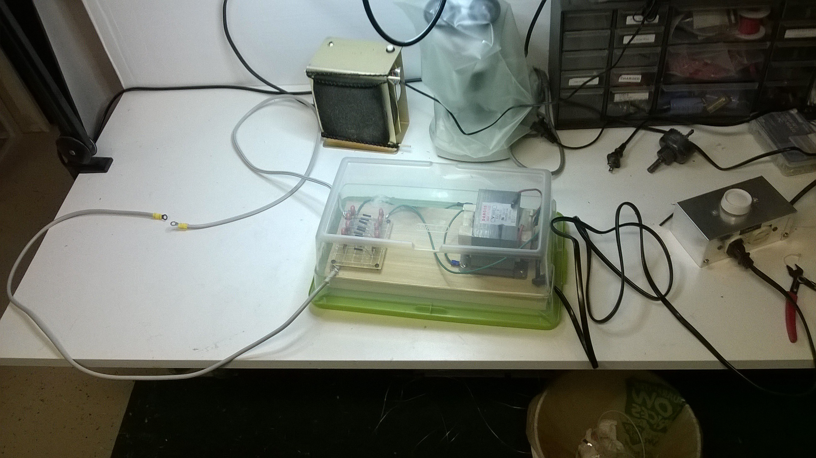
I placed the high voltage circuit inside a small plastic container to prevent me from accidentally touching it and killing myself. I screwed the components onto piece of wood with a hook so I can hang it to the side of the bucket.
All the components were finished now all I needed to do was test it!![]()
![]()
-
Second Pass: Redesign of Wetscrubber w/ Prototypes & Testing
08/16/2015 at 02:01 • 0 commentsIn 2014 up till today I have been reading and researching best practices in wet scrubber design. In my next iteration I want my design to have greater air flow without compromising performance. For my wet scrubber to be effective in removing odor, VOCs (volatile organic compounds), and smoke particles as I have intended, IT NEEDS TO BE ABLE TO REMOVE PARTICULATES THAT ARE LESS THAN 1 MICRON (UM) IN SIZE. Conventional wet scrubbers have a practical limit to the size of particles it can scrub from the air. The best wet scrubbers can scrub 99% of particles above 1um. For sub micron particles, another technique is typically used. ESP's (Electro Static Precipitators) have excellent performance for sub micron particles, matching that of HEPA. Wet scrubbers can have also have electrostatic augmentation, which is done by electrifying the dirty air before piping it through wet scrubbers and/or by oppositely charging the scrubbing liquid in the wet scrubber. I plan to use this technique of electrical augmentation for my enhanced wet scrubber invention.
To provide greater air flow without performance loss in my new wet scrubber design I knew I needed the following:
- larger piping
- higher turbulence between the air and scrubbing liquid
- longer contact time
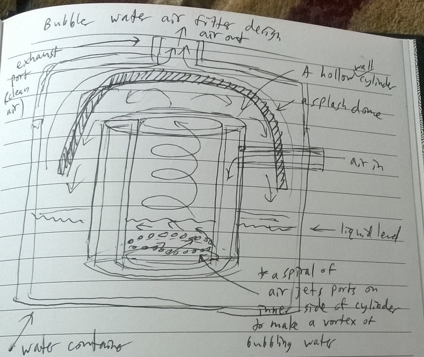
On August 14th 2014, a design dawned on me how to do just that. The wet scrubber would be a large hollow walled tube that has an inward spiraling "sieve plate" which is comprised of many nozzles directed at an angle to the tube surface, forming an inward spiral towards the center of the tube. This tube is submerged in a tank of water (scrubbing liquid) with the water level above the nozzles. The dirty air would be piped into the hollow tube wall and directed through the nozzles into the scrubbing liquid at an angle. The impact of the air hitting the scrubbing liquid separates particles from the air. As air travels through the nozzles and into the liquid, it will accelerate the scrubbing liquid into a vortex. As the vortex of liquid accelerates past the nozzles at an ever increasing speed, it will increase the impaction force between the air and scrubbing liquid, thereby increasing the scrubbing effect. The mist will then spiral upwards and exit the top of the tube. The cyclonic action caused by the spiraled nozzles allow longer contact time between the scrubbing liquid and the particulate laden air, as the misty air would travel in a longer spiraling path. The air flow would be limited only by the number of nozzles and tube diameter. At the top of the tube would be a large dome to act as a mist eliminator. The particulate laden water would spiral and impact the dome. The droplets, along with the trapped particulates, would fall back into the pool of scrubbing liquid and the clean air would exit upwards from the tank. I don't think this specific design has ever been done before so I may end up writing a patent application.
![]()
I quickly began to prototype this new idea using CD spindle cases and coffee stirrers
![]()
![]()
My initial setup made a huge mess as I did not have a splash dome on top of the tube. This design however worked wonderfully.
![]()
I wanted to see if I could make the design smaller so I experimented with a couple other prototypes of different shapes and sizes.
![]()
I strived to get the device even smaller to maintain a small counter top form factor.
![]()
![]()
To test the scrubber's effectiveness, I had it suck up activated carbon dust, and placed a paper towel at the exit port to see what got through.
![]()
I bought a compound microscope to see the results. What I found was astonishing.
This image below is the control, piping activated carbon dust unfiltered directly into a paper towel.
This is picture below is after passing through the wet scrubber![]()
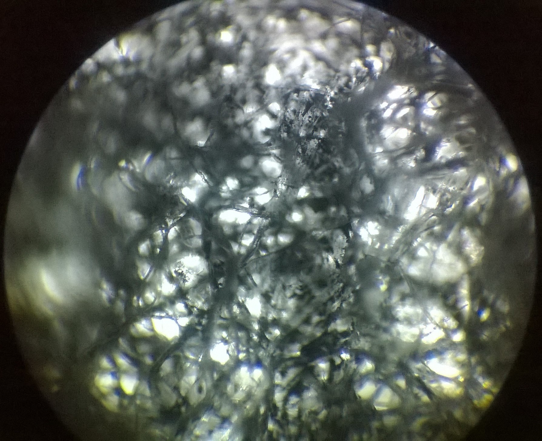
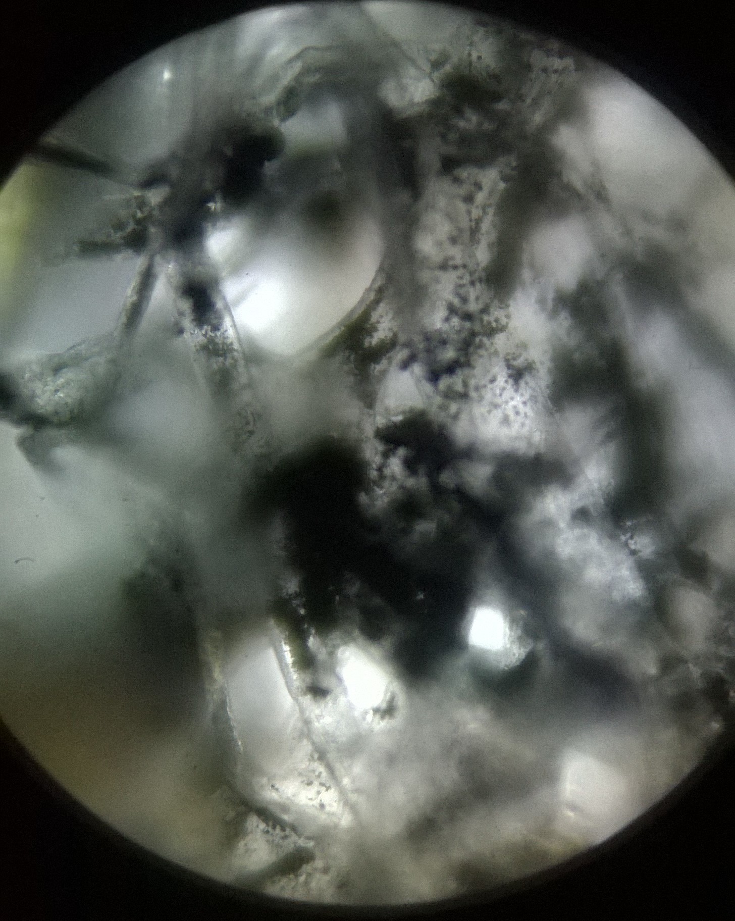
This image below is a zoomed in view of the control, piping carbon directly in to a paper towel.![]()
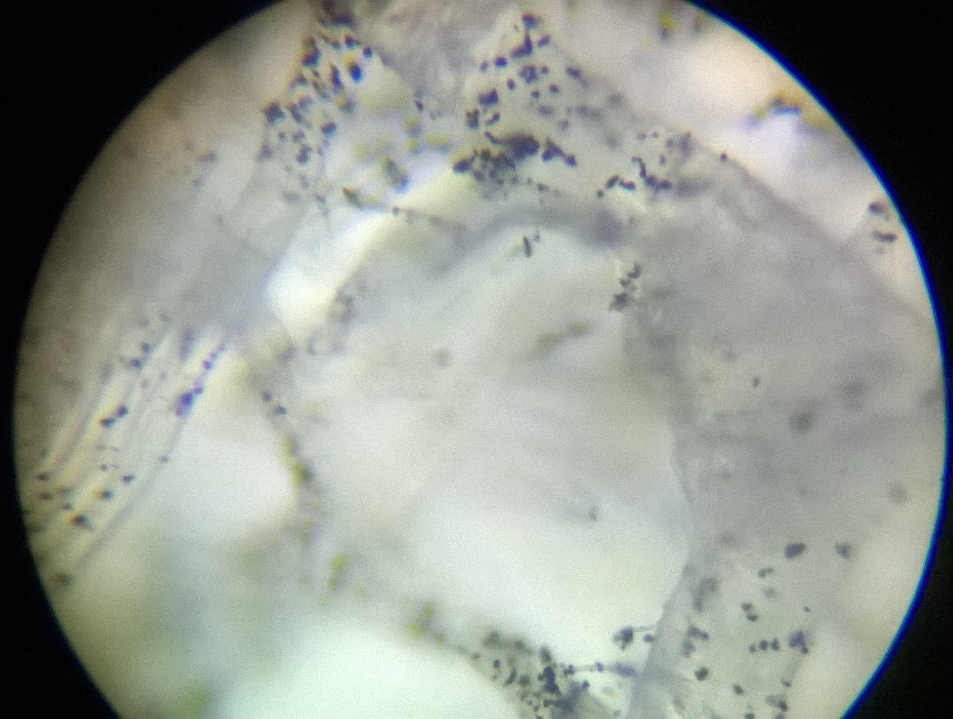
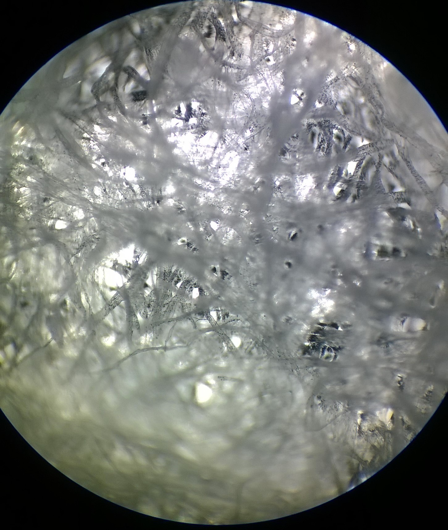
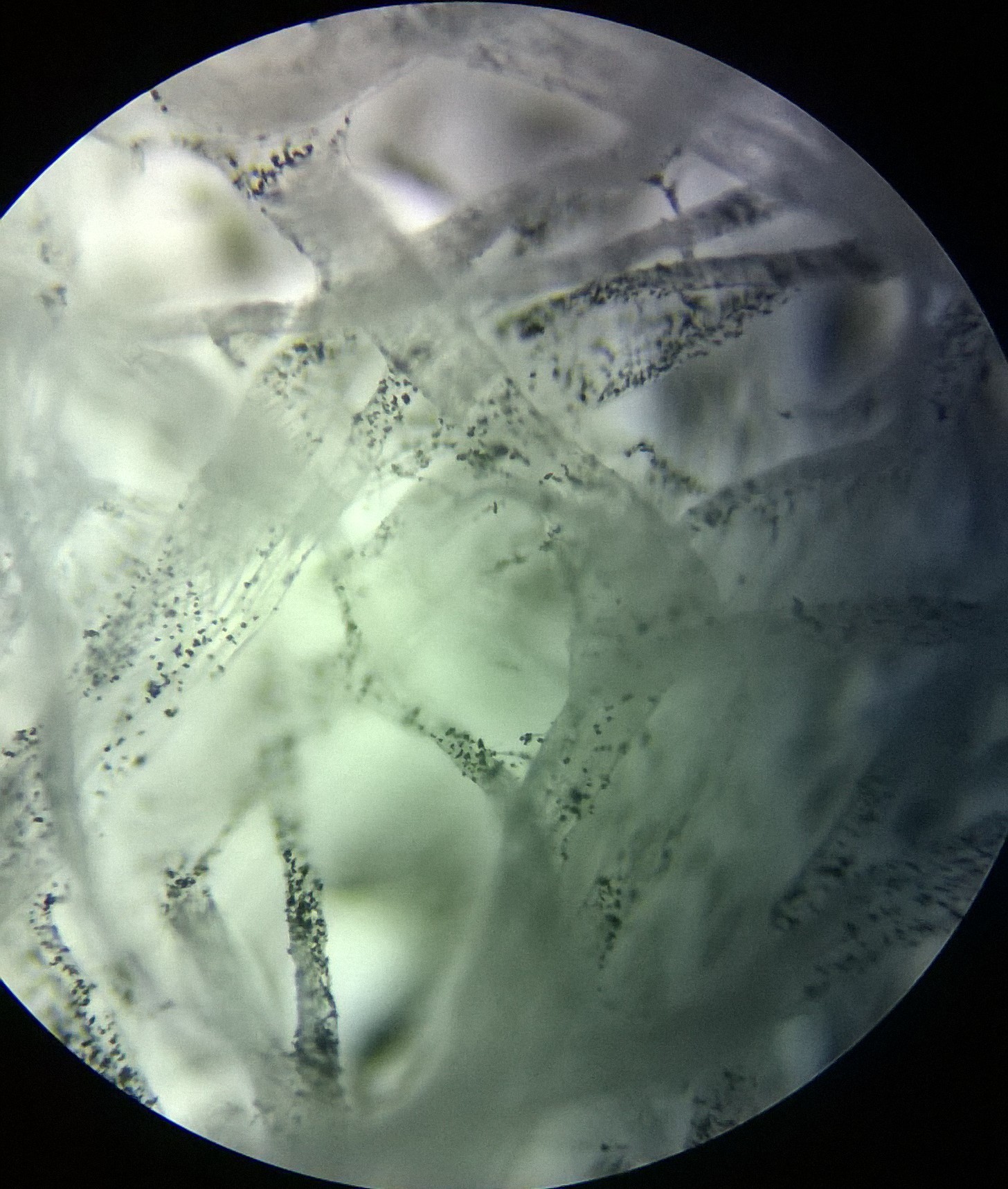
The picture below is a zoomed in view of the sample taken using the wet scrubber setup. Only the smallest particles remain.![]()
![]() This is an even more zoomed in view of the sample taken with the wet scrubber.
This is an even more zoomed in view of the sample taken with the wet scrubber.![]()
The particles that penetrated the scrubber were about 2-5um in diameter, approaching the limits of that of an orifice scrubber! Not bad for a counter top device. This is still not great however and definitely not up to par for my end design.
It was time to implement the electrostatic enhancement stage.
-
My First Pass Design
08/15/2015 at 22:55 • 0 commentsIn July 2013, I started prototyping my initial idea to use a wet scrubber as a counter-top kitchen recirculation hood. The design combines a Venturi scrubber and a sieve plate wet scrubber, and the airflow is provided by a small vacuum motor.
![]()
The entire unit is comprised of a vent hood on a boom and a tall cylinder containing the wet scrubber unit. The vent hood is mounted on a retractable boom and can be swung over a kitchen range to suck in dirty air. The wet scrubber unit consists of a Venturi nozzle set in a sieve plate submerged in water. The dirty air enters through a pipe opening in the hood and is routed to the bottom of the wet scrubber unit. The air then passes upwards through a Venturi nozzle, creating mist. The misty air impacts a cup, reverses direction and bubbles through a sieve plate. The mist is then separated from the air as it hits mist eliminator plates. The now clean air exits through the top of the wet scrubber unit. The components of this assembly is described in detail below.
The Venturi nozzle is created by inserting 3 plastic tubes perpendicularly into a PVC pipe and cutting the pipe at an angle. The entire nozzle is fitted inside a sieve plate.
![]()
This nozzle assembly is submerged in water with the water level above the sieve plate. As dirty air passes through the nozzle, the Venturi sucks water upwards and induces a spray of mist that impacts the dirty air. The impaction between particulates in the air and the water droplets in the mist encourages the particulates to separate from the air and cling onto the water.
On top of the Venturi nozzle, a glass cup forces the misty air to reverse direction. As the air impacts the wet surface of the cup and changes direction, more particles in the air are forced into the water droplets. The cleaner air then enters the water a second time, this time bubbling up through the sieve plate. This bubbling action allows more particulates to be picked up by the water through diffusion.
![]()
From there the misty air is passed through a mist eliminator, which separates the particulate burdened water droplets from the clean air. The clean air is then allowed to exit the scrubber unit.
My first prototype was made from a large glass vase, PVC pipe, Tupper ware, a glass cup, a cake container, and a small vacuum motor. Here is a video of its operation (Warning: it is rather loud!):
What I learned from this first prototype is that the vacuum motor is hella loud. The piping is way too small and does not allow adequate air flow and suction from the hood. Also in this prototype, the VOC's are not adequately scrubbed when I tested on fumes from burning butter, which means that an adsorbent bed may need to be added.
This led me to my current design, which is to use a high voltage booster stage and a cyclonic self induced spray (orifice) scrubber. This will allow for more contact time between particulates and the scrubbing liquid, along with greater air flow.
-
Testing the Electrostatic Precipitation Circuit
08/15/2015 at 09:25 • 0 commentsI had initially bought ionizer modules from a ebay. They were seriously underpowered. I went ahead and built the high voltage circuit myself using a microwave oven transformer attached to a cockcroft walton multiplier. It was frightening to see it work. After building the high voltage circuit I tested the effectiveness on clearing smoke. Here is the test in this video:
Household Electrically Enhanced Wet Scrubber
A household air purification unit for kitchens, labs, & smokers used to scrub fine particulates and VOC's out of the air.


 I then drilled a hole in the bucket so the hollow walled tube could be mounted to it.
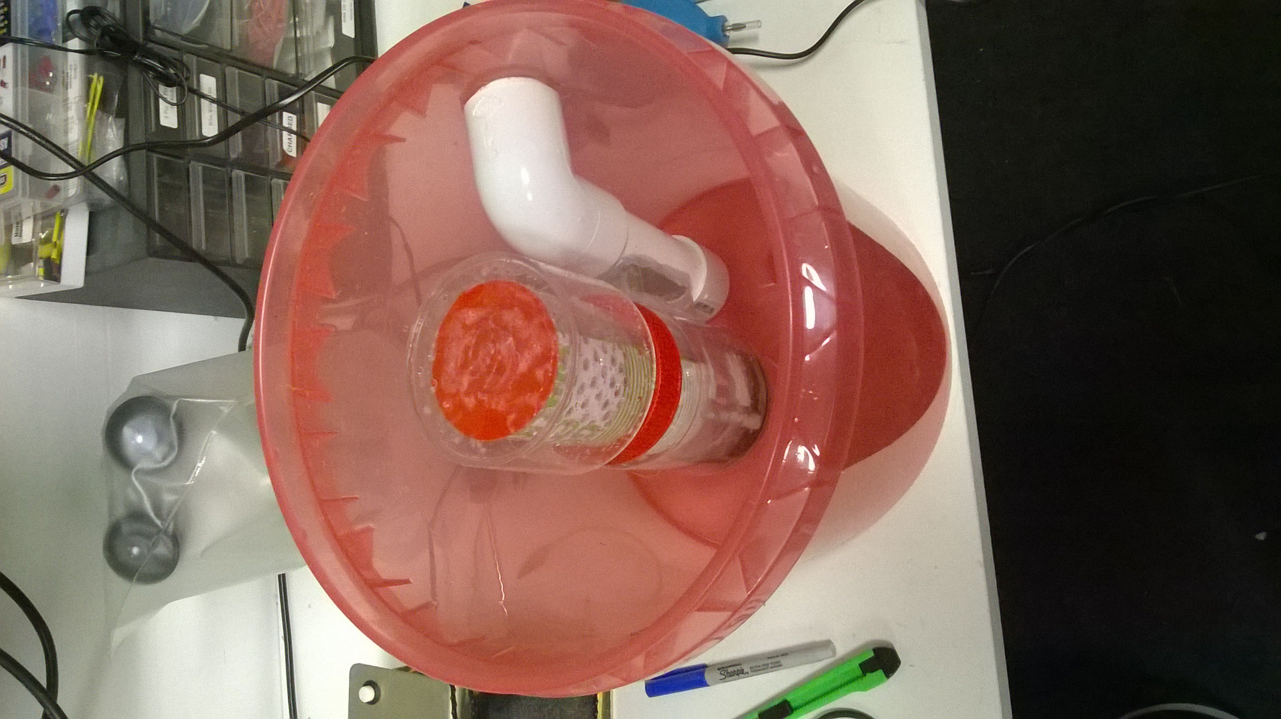
 For the mist eliminator section, I took another slice of the ABS pipe and drilled a bunch of inward spiraling holes into it and flipped it over so it spirals outwards compared to the nozzles at the bottom. These holes help continue the spiraling motion of the misty air in the inner tube until it exists in an outward spiraling fashion.
 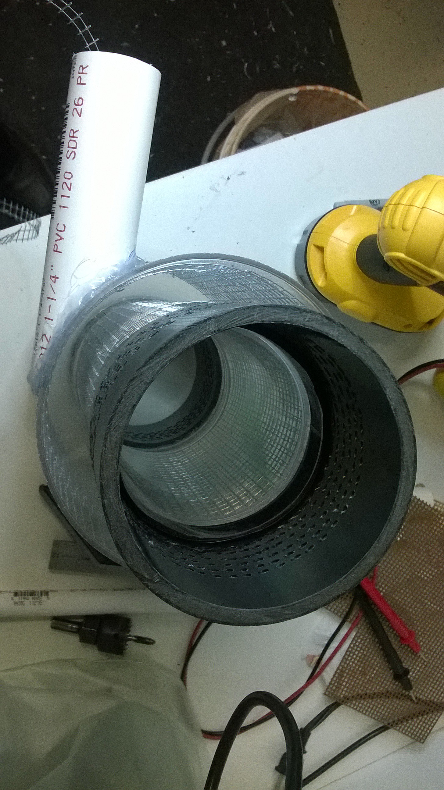 A bowl like container is placed on top of the inner tube sealing it forcing the misty air to exit the outward spiraling nozzles. As the misty air exist the outward spiraling nozzles at the top of the hollow walled tube, it will crash into the bowl that is placed over the nozzles, thereby separating the mist from the air. Note the number of holes on the outward spiraling nozzles must be equal to or greater than that of then inward spiraling nozzles so to let the misty air exit out the top and not escape out the bottom of the hollow walled tube and bypass the scrubbing action.
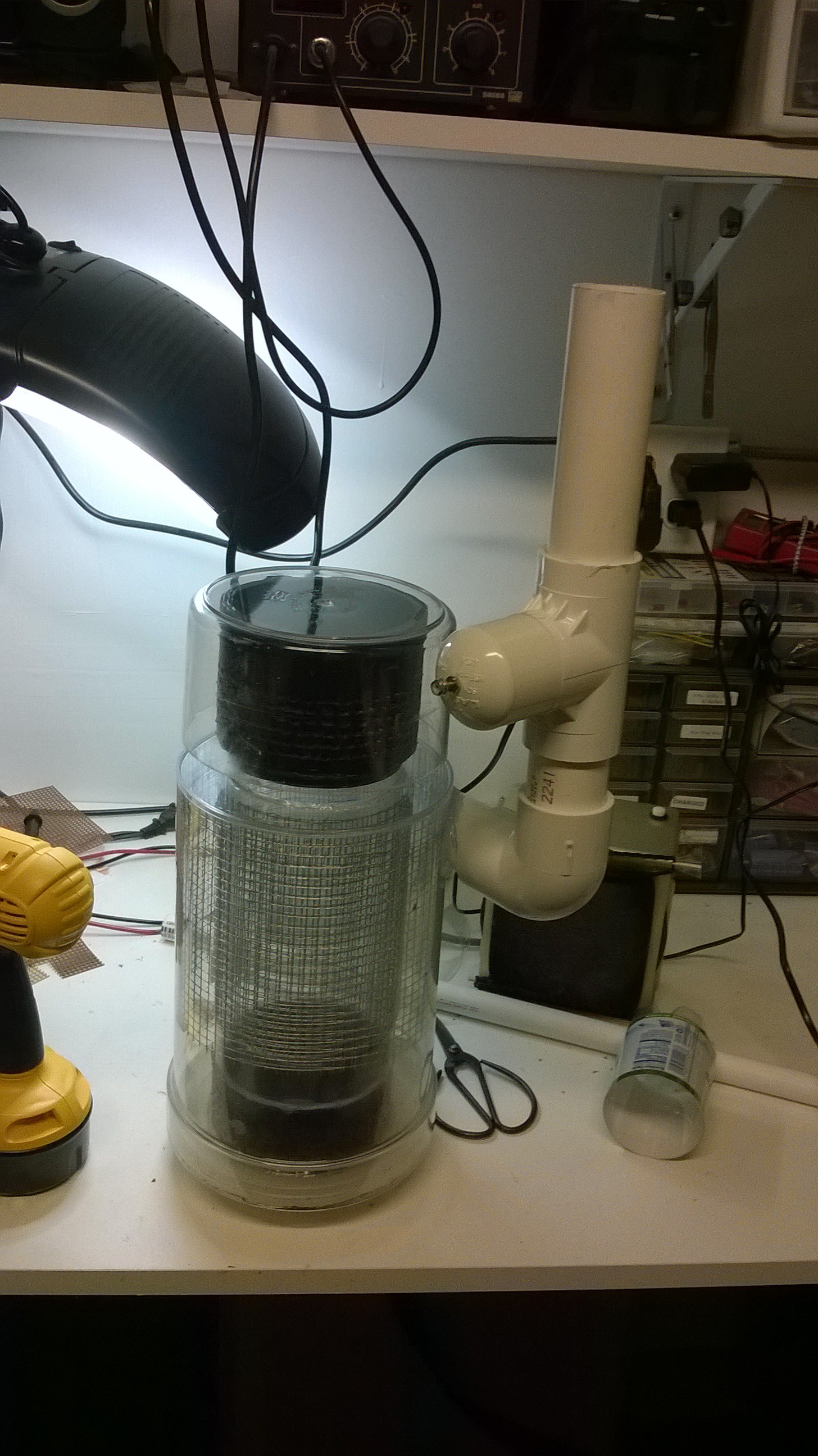 The charge grids had a wire that ran through the air inlet pipe and terminated at a screw on a PVC "T" joint. I made it this way so the high voltage circuit could easily be attached to the terminal from the outside.
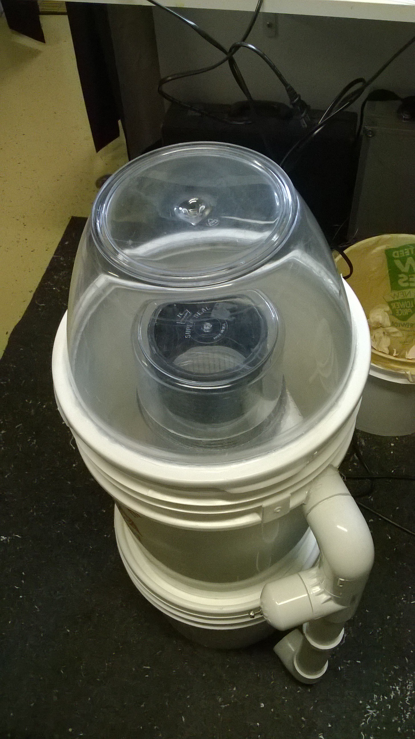


 This is an even more zoomed in view of the sample taken with the wet scrubber.