 Manuel Oexle
We use this electric motor as a generator. To get electricity you need to lift your car, disassemble one front wheel and put some kind of wood under the other wheel to make sure your car can't move. Then you mount the flange together with the generator directly to the drive shaft. At the bottom of the generator is a steel frame working as a lever to get the counterforce against the torque of the drive shaft. To find the perfect shift of your car we will add some kind of revolution counter to the generator. So you can find the perfect gear to almost match 50 Hz and you will have a power supply where ever you need.
Licences:
- Inventor Student License for the CAD Program
- Traceparts.com for the CAD-Data of the generator
Parts:
-Flange
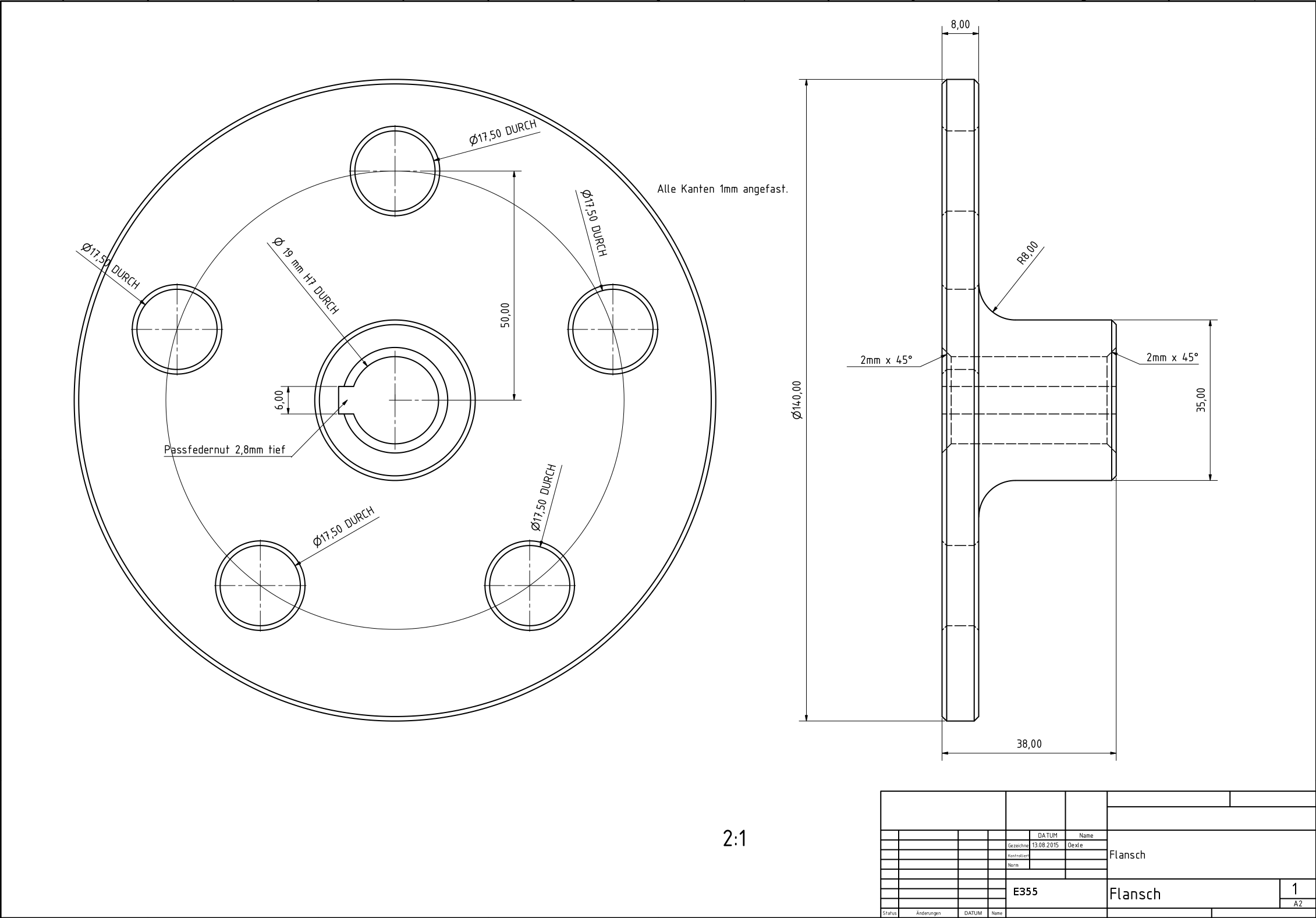
This flange only fits to a car with five wheel bolts. Flanges for other versions will follow.
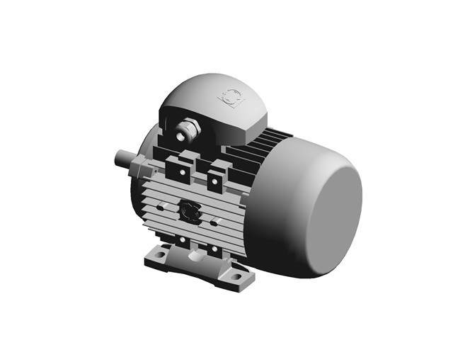
-Motor
We just bought this electric motor via a small advertisement in the internet. It was about 40 €.
At Traceparts.com we found a almost similiar motor for the Computer Aided Design Data.
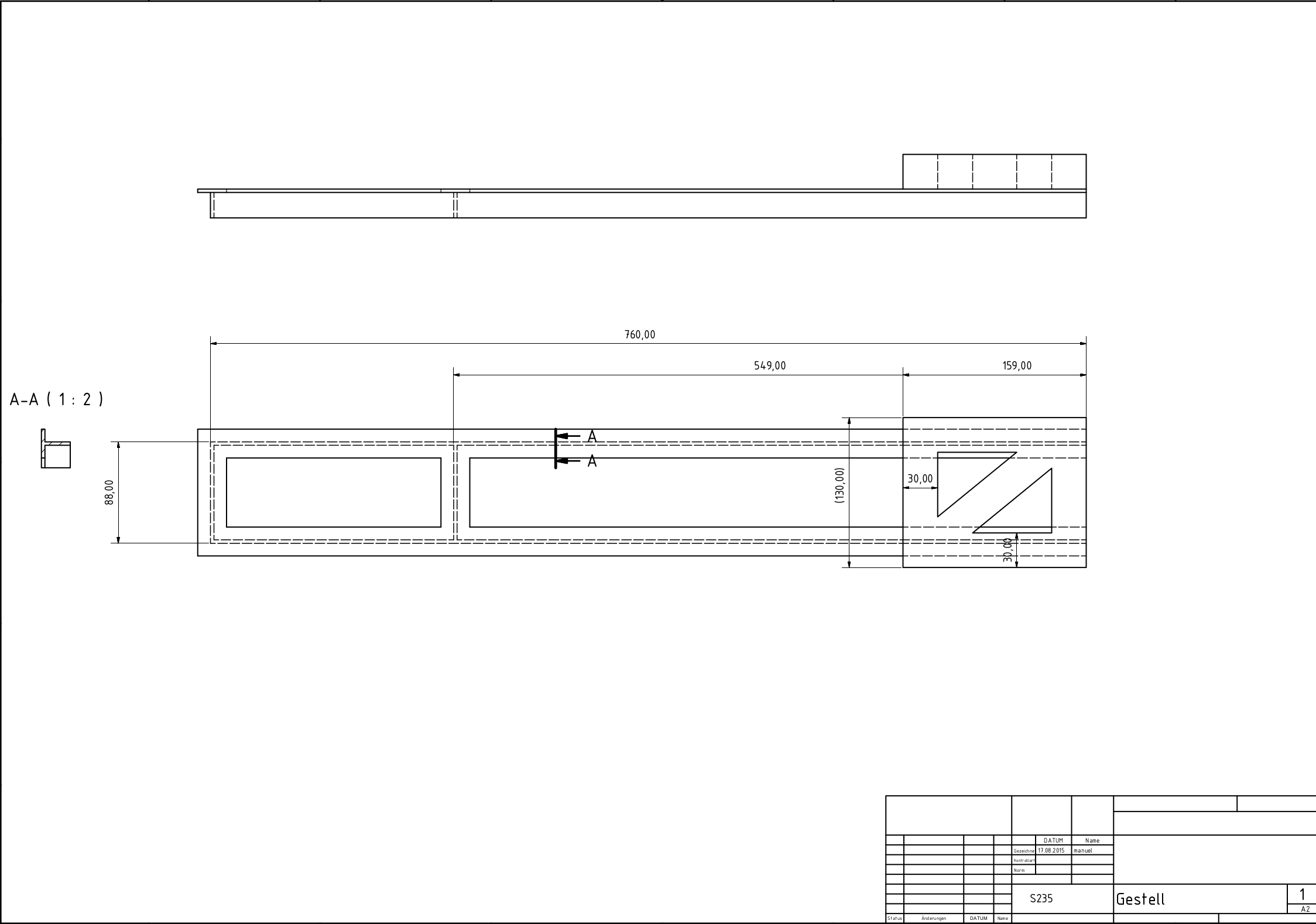
- Counter bar
As you can see in the video it is possible to use every material you have for the frame. The task of the frame is to press the force, produced by the torque of the drive shaft, through the bar to the ground. For the first prototype in the video we have just mounted a wooden bar to the electric motor. In the picture below you can see the steel frame we are going to weld.
- electric box
Inside the electric box we will install all the electric parts necessary for the generator. It will be equipped with a power socket and a frequency meter. With the frequency meter you can adjust the revolution speed to fit the 50 Hz.
We will add pictures of the flange, the frame and the electric box as soon they are finish.
 Jarrod
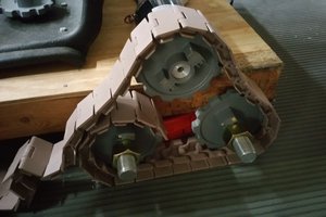

 Roddy "Rags" Read
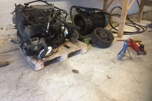
 Jesse Tolvanen