 Robin Fröjd
VESC Flier model Remove Hall Sensor Filter
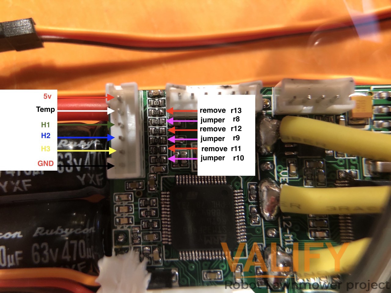
In order to get an straight connection from the input from a encoder one need to remove the hall sensor filter on the VESC, explained here
My VECS´s are slithy different then the original VESC´s created by Benjamin Vedder. The VESC I have is 4.12 PCB Flier model. The main difference between them is that the flier have moved all the mosfets one side on the PCB. This also means that the PCB layout will be slithy different.
So, In order to remove the hall sensor filter explained in the video from Benjamin one need to remove R11-R13, C5-C7 and solder jumper or a 0 ohm resistor on R8-R10.
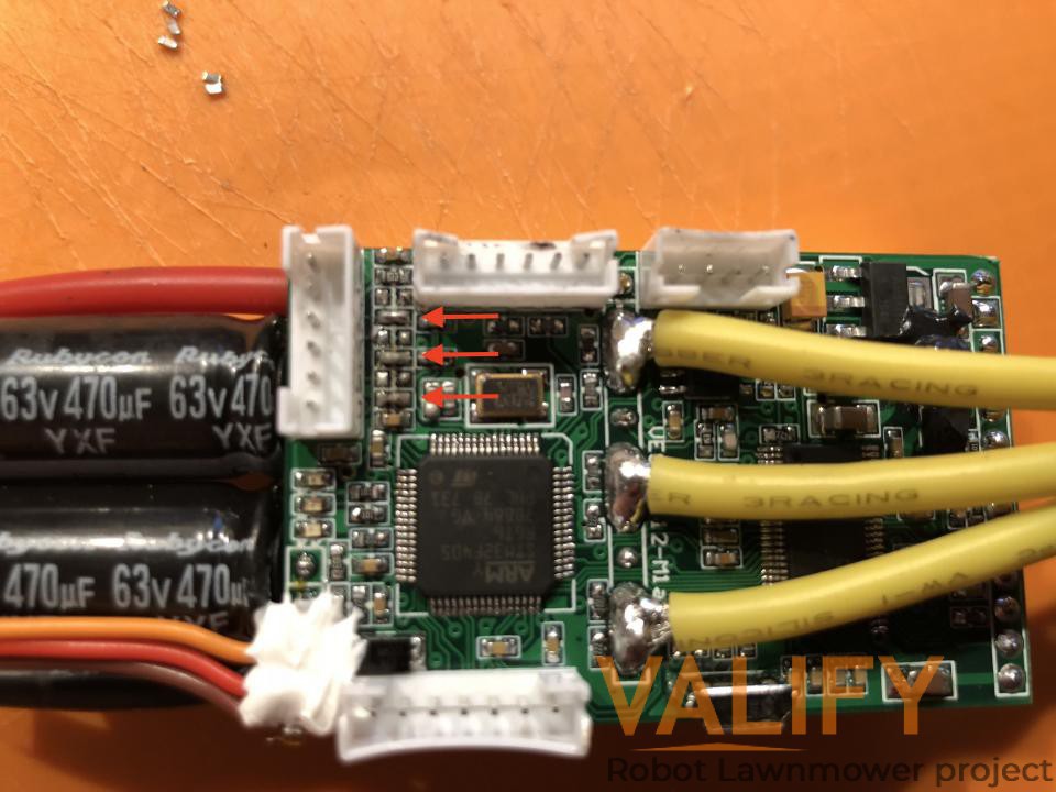
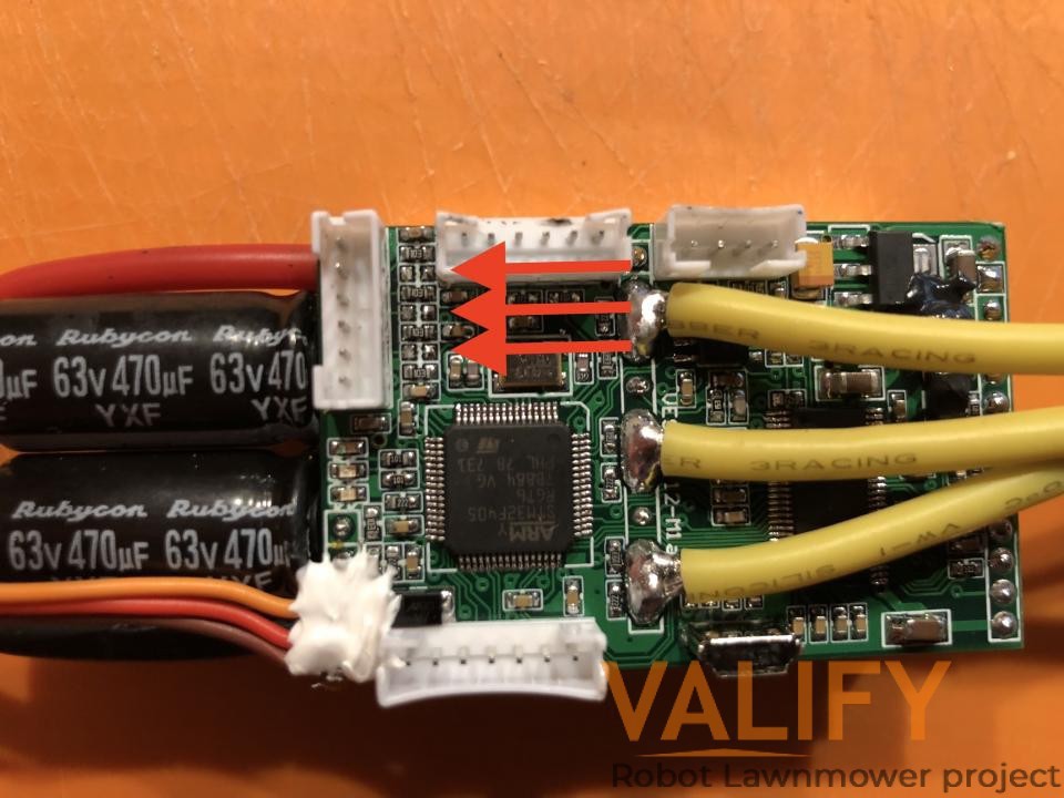
I tried to find a board schematic for the VESC flier model without success and the PCB did not have any markings as the original has. So I needed to investigate the PCB more closely to be able to find them, even if the layout is slithy different they will be located near the hall sensor filter connector. Looking at below picture you can see my conclusions on where they are located

Discussions
Become a Hackaday.io Member
Create an account to leave a comment. Already have an account? Log In.