Robin Fröjd
-
2018-04-20
04/21/2018 at 05:16 • 0 commentsSo yesterday, CNC milling of motor brackets was started.
The inside contour was finished. The outside contour is left. :)
Sketch of motor brackets 
CNC tool heads 
CNC milling inside contour 
inside contour finished -
2018-04-19
04/19/2018 at 21:39 • 2 commentsTo confirm the Field of View from the the ZR300 I did a quick assembly attaching the old nose to the robot. Here is a short video on the field of view running ROS and RVIZ with a image and a depthcloud. enjoy!
-
2018-04-19
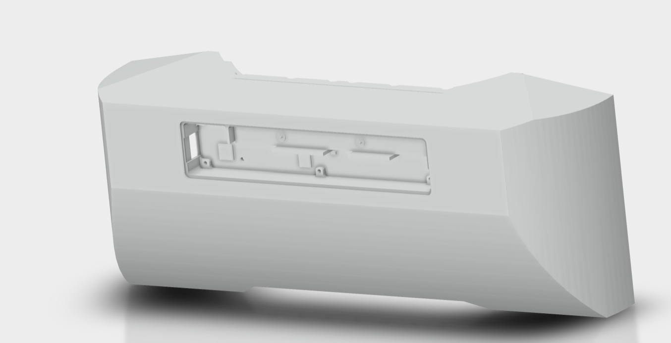
04/19/2018 at 21:37 • 0 commentsToday I finished with the design of the new nose.
![]()
New design nose Before printing the new nose I decided to print only the housing for the ZR300 camera. The partly printed part came out great. The main modification from the original housing is that the housing is made deeper so the PCB can be mounted deeper allowing the USB head to be mounted in the USB socket (not possible before)

3D printed zr300 camera housing 
3D printed camera housing intel realsense -
2018-04-17
04/17/2018 at 12:44 • 0 commentsTesting the 3D printed front nose. Looks quite good. Minor adjustments needs to be done.
Printed with PrimaSelect PETG @240C, 85C bed, 3shells and 15% infill (Very solid outcome).
-Countersink need to be adjusted to cut the body.
-The Integrated ZR300 camera need some cover on the back.
-Check if one can use a 90 degree USB instead of a normal USB head.
Raise3D n2+ Printing robot nose 
3D printed robot nose 
3D printed nose test assembly -
2018-04-15
04/15/2018 at 11:54 • 0 commentsTonight I 3D Printed mounting brackets for the front wheels. I have acquired some cheap and simple testing wheels which will be used before I spend time and effort designing my own with proper bearings. My final wheels will also be more ball-like, so they want stuck as easy in terrain. Before doing the design I also want to test some different heights for the front wheels, with the first test wheels the robot will have a zero degree vertical angle. I want to test to use slightly bigger wheels and increase the vertical angle. If an vertical offset angle can increase the performance when cutting higher grass, meaning the cutting blade will trim the top of the grass stem at the vertical offset angle max degree and the min degree will cut the rest of the grass stem to the desired level. When the robot is up and running I will measure power consumption with different angles, check the cutting quality and compare how high grass the different angles can handle.

Cutting blade angle The 3D printed brackets came out great. Following the contours of the body and blended in quite good. This parts was also printed with PETG.

3D printed wheel brackets A quick and dirty assembly with all wheel mounted.

Quick assembly of robot 
Quick assembly of robot 
Quick assembly of robot Saturday’s late night fun ended with playing around a bit. touchscreen, USB ports and external HDMI port for ease and ability to change and program on the fly when outdoors. what do you think?
A very quick and messy under the hood picture. This is not how it will or should look like. The final assembly will shine!

Valify robot under the hood -
2018-04-11
04/10/2018 at 12:43 • 0 commentsSo this weekended I have been working on finishing the design of the drive system. I have updated the initial design of the 2-pulley gearing into a 4-pulley gearing. The main reason for the update is to have the ability the to achieve a lower wheel surface speed. The brackets are also designed with adjustable offsets, so each component can be adjusted to tighten the belt, or allowing a easy change off pulley sizes without redoing brackets.

Drive System Design Completion
My goal is a 0.4m/s wheel surface speed. Would give me 0.4*60/0.7225=33 RPM on the wheel shaft. So I am within the limits to achieve that. So this is the final design of the drive system.
Drive System Design Completion Hopefully this week, CNC milling of motor brackets begins.
In the meantime I keep the printer busy with printing pulleys.Sizes printed today is XL 10T, 50T and a 55T. Took a few test prints before I could find the sweet spot for the settings for a maximum belt grip.

3D printing drive belt pulleys -
2018-04-06
04/07/2018 at 10:21 • 0 commentsRotary Position Sensor + VESC
As it turns out you do not really need to make modifications to remove the hall sensor filter in order to get Rotary Position Sensors to work with the VESC. In a previous post I described how I located the hall sensor filter and removed it (read here).
Anyways, I was looking around the internet and found this blog which describes how to do it.
there is actually another port on the board you can use that is faster (hardware SPI instead of software SPI) and does not require previous mods mention here – just a change in a header file for the firmware.
By uncommenting this line in conf_general.h will enable the Hardware pins
#define AS5047_USE_HW_SPI_PINS 1
When changes have been made you need to compile the firmware and upload it to the VESC.
The Hardware pins is located here:
It has the following pin layout (JST–PH 2mm 7pin)
5V - 3V - GND - Clk - CSn -MOSI -MISO
To connect the Rotary Position Sensor simply connect the corresponding ports to the VESC. I use the 3V and leave the 5V empty. It also highly recommend to use a shielded cable or try to keep the wires below 7 cm to reduce electric noise.
In my earlier post I connected the AS5048A over Software SPI on the hall sensor ports and had problems reading 0-180 degrees rotor position, but 180-360 degrees worked perfect. I posted a topic on the VESC forum an got a suggestion to ignore the MSB and use 13 bits instead of 14 with the following code in encoder.c
void encoder_tim_isr(void) {
uint16_t pos;

spi_begin();
spi_transfer(&pos, 0, 1);
spi_end();

pos &= 0x1FFF;
last_enc_angle = ((float)pos * 360.0) / 8192.0; }
It worked perfect, I could now read 0-360 degrees rotor position with the AS5048A. The Rotary Position Sensor was running 13-bits, 8192 positions per revolution. So not optimal for a Rotary Position Sensor with 16384 positions per revolution. Please note that this fixed the problem with Software SPI over hall sensor port.
The guy that I wrote about earlier in the post also had an alternative BLDC stack for his rover, which included a modified encoder.c with changes to keep track of the continuous encoder position. Connecting the VESC to the hardware SPI and uploaded his modified stack to the my VESC solved all problems, I was now running hardware SPI with 14-bits (16384 positions per revolution).
The AS5048A does not allow ABI interface, the AS5047P and the AS5047D does. I previously connected the AS5047D over ABI @2000 positions per revolution sucessfully. A disadvantage of the ABI mode is that it only gives a valid angle after detecting the index pulse. In SPI mode a valid angle is provided from the start.
Here is a small test of the AS5048A Rotary Position Sensor with the temporary drive system. Motor brackets are still 3D printed and not perfect (waiting for CNC Milling), therefore some annoying noises! Running VESC FOC Mode @10% Duty.
-
2018-04-04
04/05/2018 at 12:51 • 0 commentsTesting the touchscreen and the Scanse Sweep.
-
2018-04-02
04/03/2018 at 06:31 • 0 commentsAS5048A Rotary Position Sensor + VESC
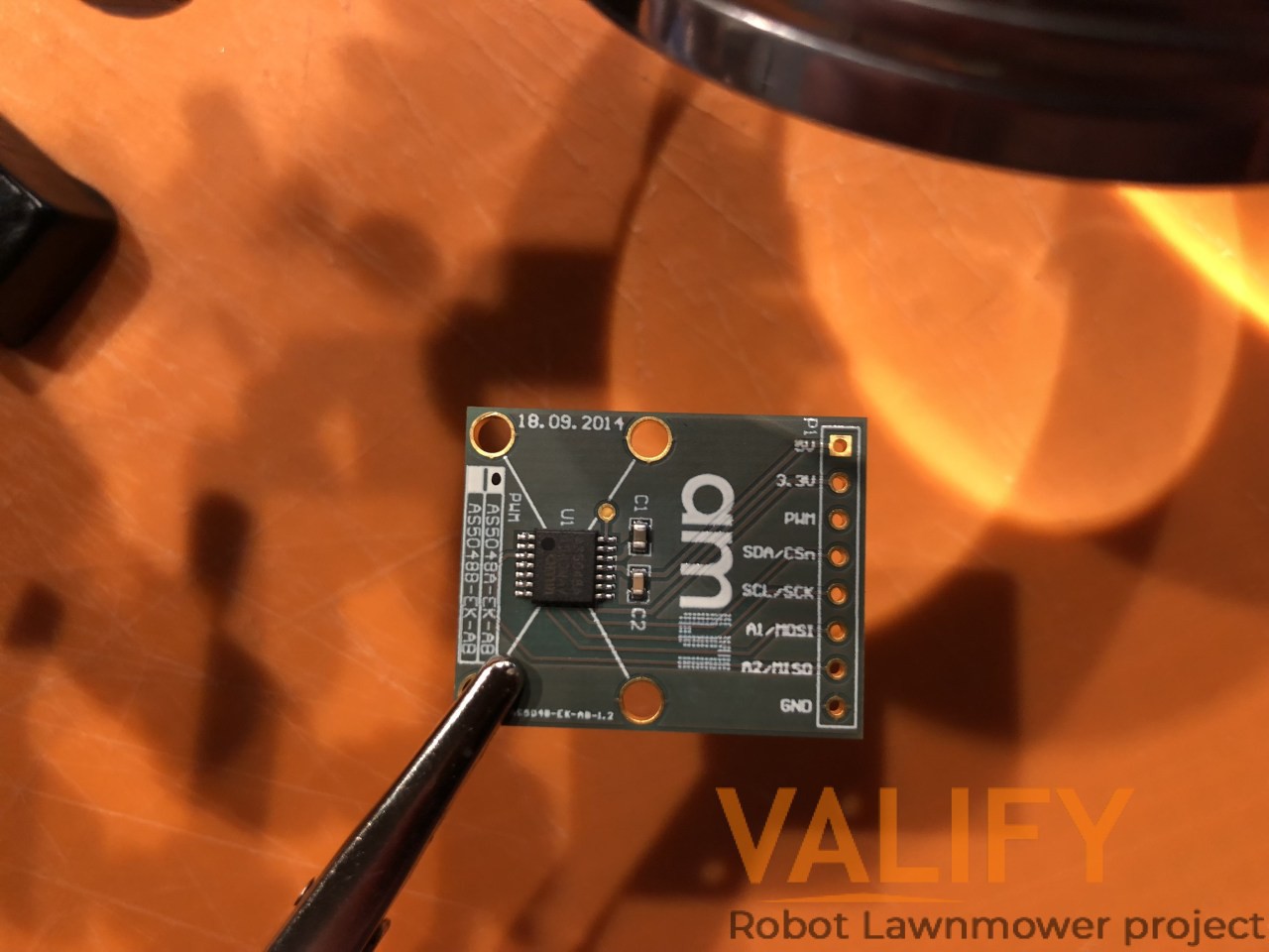
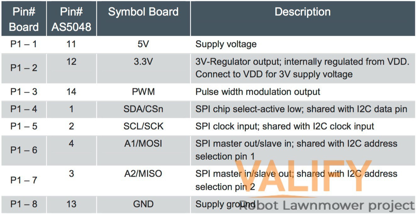
Yesterday I received a bunch of different encoders that I will test one by one In a near future. Lets start by with the ams A5848A. The AS5048A is a 14-bit rotary position sensor (previously known as encoder) for absolute angular measurement and with a PWM (=pulse width modulation) output over a full turn of 360° based on contactless magnetic sensor technology.
The PCB is available in two versions. Either with an AS5048A with SPI or AS5048B with I2C interface. P1 has to be populated with a 1×8 pin header and is required for power supply as well as SPI/I2C and PWM interfaces
![]()
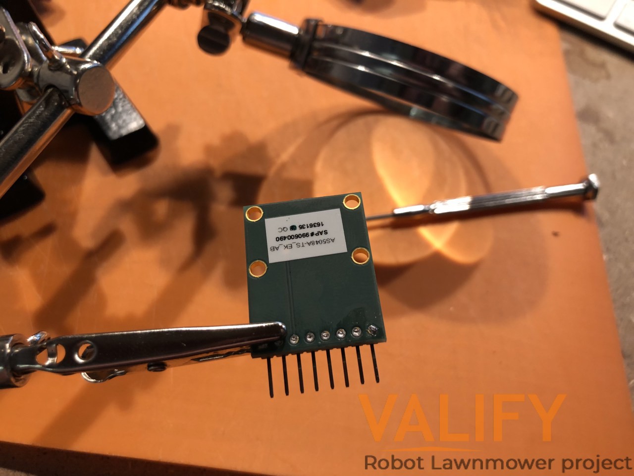
The PCB is quite tiny and have the dimensions 28x22mm, making it fit almost everywhere. The thickness of the PCB is 1.8mm and with PCB and the AS5048A chip is 2.8mm. The 6×2.5mm diametric magnet (that comes with the dev board) must be placed over or under the AS5048 sensor, and should be centered on the middle of the package with a tolerance of 0.5mm. The airgap between the magnet surface and the package should be maintained in the range 0.5mm to 3mm.
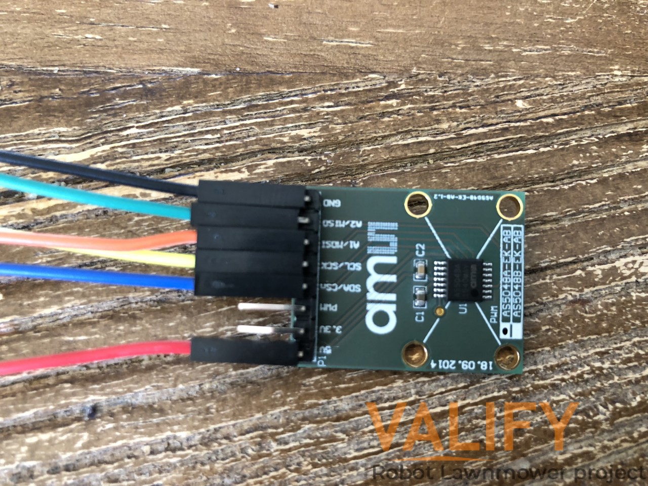
I started by soldering a 90 degrees 1×8 pin header to the PCB. I went with a 90 degrees pin header because of the limited space in my setup. Soldering at a tiny PCB like this was the first time for me. But I think it came out quite good (Feedback always welcome).
![]()
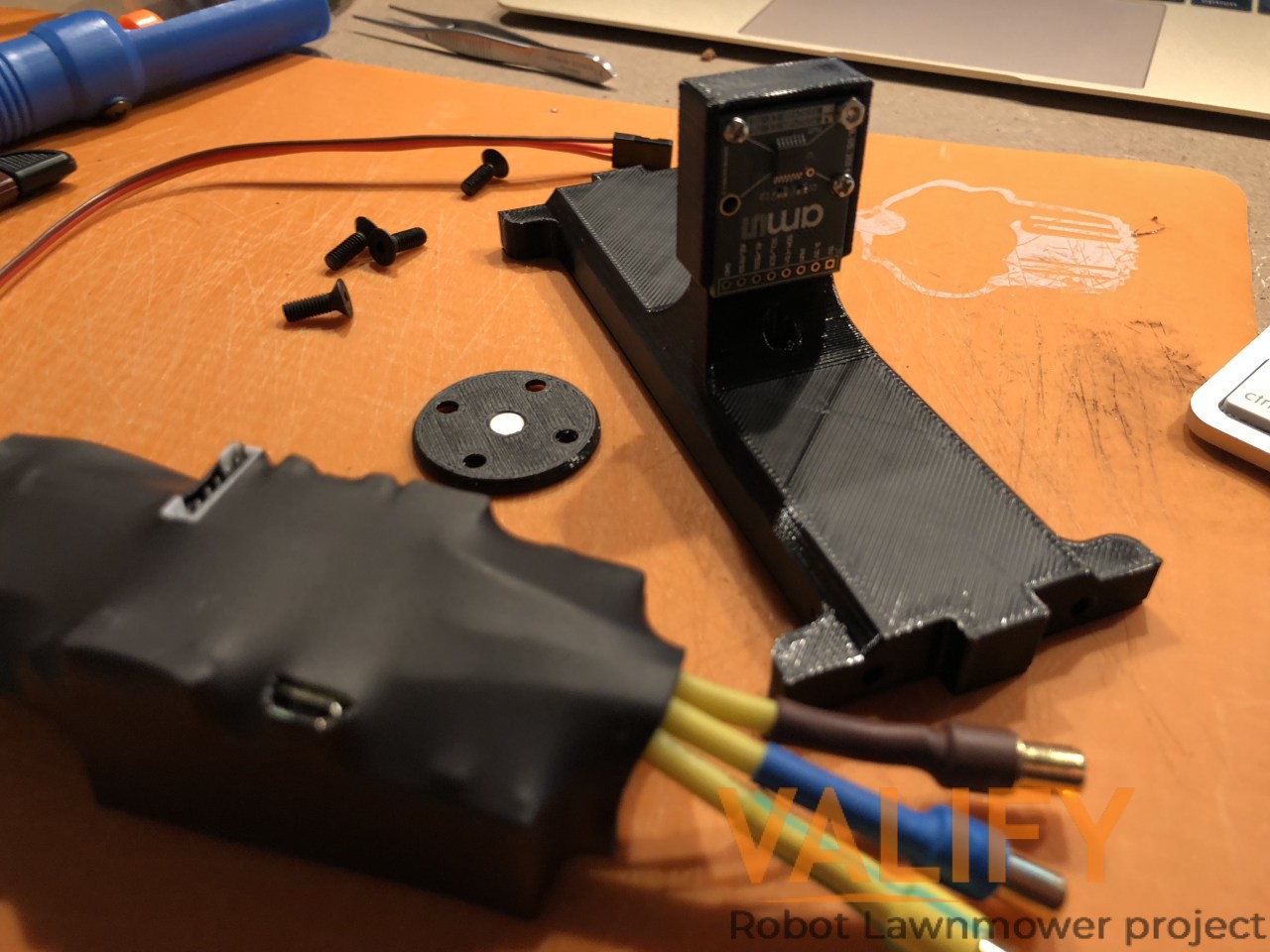
In order to test the encoder with my motor I made an encoder mount that will be mounted between the motors brackets. The mount will hold two AS5048A encoders, one for each motor. In my design the air gap between the AS5048A chip and diametric magnet is 1.70mm. The first prototype of the encoder mount came out Ok, but some minor adjustment needed for next version. I want to make more space for the cables (increasing the hole-size which the cables should go through).
In order to test the encoder with my motor I made an encoder mount that will be mounted between the motors brackets. The mount will hold two AS5048A encoders, one for each motor. In my design the air gap between the AS5048A chip and diametric magnet is 1.70mm. The first prototype of the encoder mount came out Ok, but some minor adjustment needed for next version. I want to make more space for the cables (increasing the hole-size which the cables should go through).
![]()
Before mounting the PCB to the mount I needed to connect the cables to the pin header because of the limited working space. The AS5048A will use SPI for communications with the VESC. The cable connection as below
SCL/SCK (P1-5) -> HALL 1
A2/MISO (P1-7) -> HALL 2
A1/MOSI (P1-6) -> VCC
SDA/CSn (P1-4) -> HALL 3
GND (P1-8) -> GND
VCC (P1-1) > VCCAS5048 adapter board and pinout
![]()
I connected the AS5048A as the pictures shows below. The VCC(Red) is bridged with (MISO)
![]()
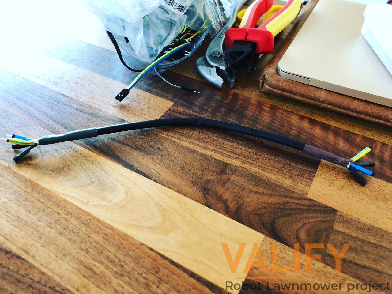
This cables was giving me to much noise. So in order to reduce the noise I used an shielded network cable with 8 leads in twisted in pairs. Each twisted pair gave me one lead. I put the VCC without any shield as a separate cable. I used the ground pin to connect the S-GND for the cable foil.
![]()
With the new cable things started to look a lot better. Encoder detection worked fine but I could not get any measurements for 0-180 degress. from 180-360 degress it works fine. I have not yet found any solution for this. But will keep trying to figure this out.
-
2018-04-01
04/03/2018 at 06:27 • 0 commentsVESC Flier model Remove Hall Sensor Filter
In order to get an straight connection from the input from a encoder one need to remove the hall sensor filter on the VESC, explained here
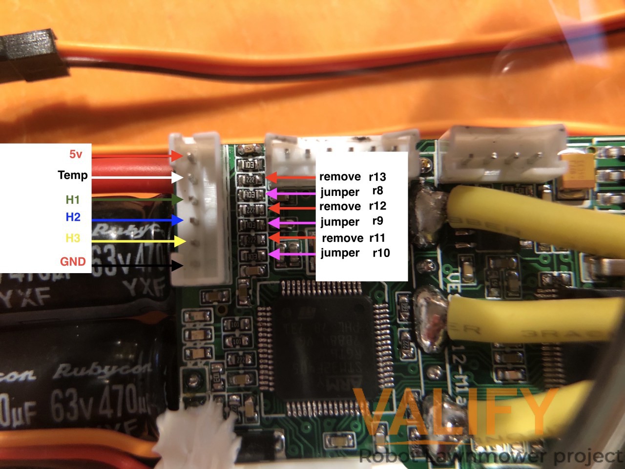
My VECS´s are slithy different then the original VESC´s created by Benjamin Vedder. The VESC I have is 4.12 PCB Flier model. The main difference between them is that the flier have moved all the mosfets one side on the PCB. This also means that the PCB layout will be slithy different.
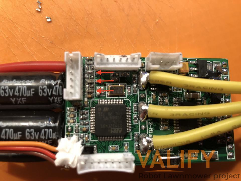
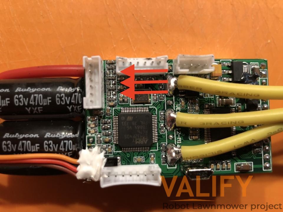
So, In order to remove the hall sensor filter explained in the video from Benjamin one need to remove R11-R13, C5-C7 and solder jumper or a 0 ohm resistor on R8-R10.
I tried to find a board schematic for the VESC flier model without success and the PCB did not have any markings as the original has. So I needed to investigate the PCB more closely to be able to find them, even if the layout is slithy different they will be located near the hall sensor filter connector. Looking at below picture you can see my conclusions on where they are located
![]()
![]()
![]()
![]()
Valify V2 Robot Lawnmower
3D Printed Jetson TX2 based robotic lawnmower aims to build an "smart" robotic lawnmower using open technology