 Chris Chung
The intermittent hardware problem became obvious when I finally had the bootloader caused "bricking" issue resolved.
This is my first project that involves a LQFP device w/ 0.5mm pitch. When I was prototyping the project with the initial PCB designs, I had trouble hand soldering the MCU. After some research on the web, I tried and explored different methods, including stencil mask, baking it in an oven, etc. It took me about 6 or 7 PCBs and a few toasted MCUs I finally settled on a drag soldering method, which gives better and more consistent results.
Visually inspected solidly soldered boards still failed (not all) intermittently after use, typically this can happen after a few days to a few weeks. Most of them can be repaired via solder re-flow and sometimes a replacement PCB.
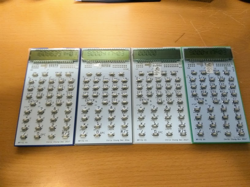
I had gone through 6 or 7 versions of PCB, and although there are improvements after working on trace length / size and ground planes, I still cannot eliminate this intermittent hardware failure. Unlike the bootloader problem which makes the calculator fails while executing, the hardware failure is more straightforward in that the calculator will refuse to start, or the charge pump will fail to attain LCD voltage, in turn fails the LCD display.
As a hobby level project, there is not much I can do except to do my trials and errors. I did tried and included troubleshooting code (like watchdog timer use) that the MCU can provide and can sometimes sees how things failed from the MCU perspective, the originating cause, however, is hard to trace.
The fact that the problem is intermittent suggested that it may be environmental. Did they fail more when the weather is dry? Or near a washer or dryer when they start to operate? How is ESD affecting the unit? I recalled the times when I was working in retail, seeing POS machines resetting themselves when a nearby ice cream fridge had it's condenser started spinning.
As a hobby level lab (and one without an O-scope), we improvised. I built this EMC testing rig from a $1 BBQ lighter. This particular lighter is easy to modify. After removing a sleeve and ring there is already a ground lead exposed.
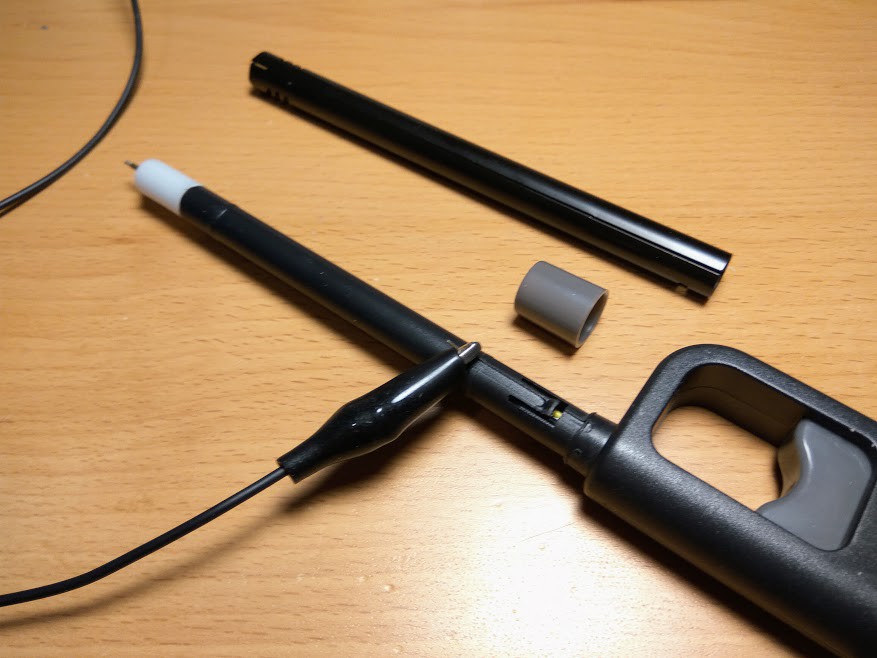
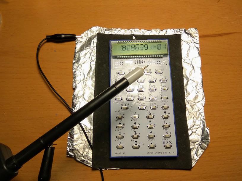
I would just need to use alligator clips to attach it to my ground which is a fold of aluminium foil where I would place the test unit on top. I would fire the lighter at a distance from the calculator and observe. When close enough the calculator under test would reset itself.
When I started to perform this test, I already had 5 different PCB designs.
By measuring the distances between the lighter and the calculator of different designs I can decide which design is more robust against ESD. I then focused on the best design and build multiple units.
The best PCB design improved the situation but did not eliminate the intermittent fails. Other facts from the ESD testing includes;
- I can improve the ESD tolerance by adding ground shield (aluminium foil) to the simple 3D printed case.
- If I fire ESD close enough and fire successively, I can kill a MCU.
I had since somehow concluded that this is caused by my soldering process and there is not much I can do about it.
As a hobby project, I am satisfied and happy with my results. I still have a few working units that I built and the oldest unit had been working for 2 years on the same battery. I used the calculator whenever I need to and sometimes will play with the programming and they are all fine for this purpose. It is fine because I created the project and if there are little glitches (button failed, segment missing due to cold solder), I can fixed that in one minute. Even if the unit failed to start, I will be able to fix it by re-flowing the MCU. This (the quality of the project) is not unlike many projects I created before.
For a kit project offering, this is very different though. I can give away these for my friends and if they failed next month, I could take them back and have them fixed. And when you sold these over the world (for my NP-25 project, I sent 100+ units to at least 15 countries), having them fixed is not that easy and economical. As I had mentioned in the comments section, my first batch of 10 units offered had 6+ units returned for repairs. It does no good to my customer and myself when they are these unreliable. So I had suspended offering them until I can reach a completely robust solution.
With the conclusion (I hope it is correct) that the problem lies on my manufacturing skills, the next logical step is to have it soldered professionally. And this is what I intended to do next. This may cost more and involve more logistics (parts, firmware flashing, shipping etc), but I think it is necessary if the project is to be offered as a product / half-kit.
Discussions
Become a Hackaday.io Member
Create an account to leave a comment. Already have an account? Log In.
Hi Chris. Nice project. I have a dozen different HP RPN calcs, and its what I use day to day. Send me the project schematics and PCB and I can help you sort it out. There will be four areas
1) the obvious ESD dangers
2) power supply control and behaviour
3) physical board deformation. Anything with human pushes on it all the time needs to be stiffened up unless designed for flexing. This is including-
a) the PCB (VIA integrity ....b) solder joints, ...c) passives - alignment direction is important.
QFP 0.5mm is really a very easy size to work with, I recommend sticking with it.. As long as you have a good microscope or head visor and appropriate soldering iron tip.
You can catch most bad joints by a basic accelerated life test using a autoclave used for sterilization. Be sure to dry after, if the components will tolerate it, vaccuum dry,
glen
canberra, Australia,
Are you sure? yes | no
Thanks for the update! Perhaps I'll take this as a warning about 0.5mm pitch - which is interesting because I had been discussing that elsewhere, as to whether it's practical for a hobbyist and drag-soldering.
Are you sure? yes | no