Actually an ultrasonic sensor goes click.. click... Anyway let's start. The lidar was mounted at a height of approximately 71 cm from the ground. That would mean that any obstacles short than that, and there are plenty of those, will not be detected by the lidar. This would make collision avoidance difficult to say the least.
So what we planned was to have an array of inexpensive distance sensor, we chose ultrasonic sensors, to be mount close to the ground of collision avoidance. Infrared range finders also foot the bill if it was'nt for the fact that they don't work very well outdoor conditions or area fill with infrared light.
We chose the most inexpensive ultrasonic sensor we can find the Devantech SRF02:

It has a working range of about 15 cm to 300 cm making it suitable for our purpose. The working minimum distance is due to the fact that there is only one transducer which both generates the pulse and receives it. After sending a pulse, the transducer needs a certain amount of time to 'ring down'. This ring down time corresponds to a minimum working distance. If you really want to get a smaller minimum working distance from these sensors, you would need to use one to send the pulse and another to receiver it. Ultrasonic sensors with two transducers do not suffer from this issue.
The SRF02 can output distance in cm, in, and microseconds (used with speed of sound to calculate distance) over serial or I2C. It runs on a 5V supply. For our purpose, we would be using I2C communication as it allows up to 16 sensors to be chained together.
For controlling the sensor we used an Arduino Leonardo. No special reason for this choice other than it has a dedicated SDA and SCL pin. Ideally there should be a pull up of the two lines to 5 V using a 10 k resistor. However using the wire Arduino library should enable the internal pull up resistor.
The first order of business was to give each sensor an unique address. A caveat here is that the SRF02 uses a 8 bit addressing while the Arduino I2C uses 7 bit addressing. The way to convert from 8 bit to 7 bit addressing is to take the 7 highest bits of the 8 bit address.
When you power up the SRF02, it would flash its onboard led, a long pulse followed by a series of short pulses which indicate its address. For explanation of address changing, you can refer to http://www.robot-electronics.co.uk/htm/srf02techI2C.htm.
We have attached here the code for changing the address of the SRF02. As the credit shows, it was modified from codes written by Nicholas Zambetti and James Tichenor
// I2C SRF02 Devantech Ultrasonic Ranger Finder
// by Nicholas Zambetti
// and James Tichenor
// Modified by Poh Hou Shun

// Address chnage of Devantech Ultrasonic Rangers SFR02

// Created 24 September 2015

// This example code is in the public domain.

#include

void setup() {

  Wire.begin();                // join i2c bus (address optional for master)
  changeAddress(0x71, 0xF6);   // change address, changeAddress(oldAddress(7 bits), newAddress (8 bits))
}

void loop() {}

// The following code changes the address of a Devantech Ultrasonic Range Finder (SRF02)
// usage: changeAddress(0x70, 0xE6);

void changeAddress(byte oldAddress, byte newAddress)
{

  Wire.beginTransmission(oldAddress);
  Wire.write(byte(0x00));
  Wire.write(byte(0xA0));
  Wire.endTransmission();

  Wire.beginTransmission(oldAddress);
  Wire.write(byte(0x00));
  Wire.write(byte(0xAA));
  Wire.endTransmission();

  Wire.beginTransmission(oldAddress);
  Wire.write(byte(0x00));
  Wire.write(byte(0xA5));
  Wire.endTransmission();

  Wire.beginTransmission(oldAddress);
  Wire.write(byte(0x00));
  Wire.write(newAddress);
  Wire.endTransmission();

}

/*

  Address 8 bit -> 7 bit map

  0xE0 -> 0x70
  0xE2 -> 0x71
  0xE4 -> 0x72
  0xE6 -> 0x73
  0xE8 -> 0x74
  0xEA -> 0x75
  0xEC -> 0x76
  0xEE -> 0x77
  0xF0 -> 0x78
  0xF2 -> 0x79
  0xF4 -> 0x7A
  0xF6 -> 0x7B
  0xF8 -> 0x7C
  0xFA -> 0x7D
  0xFC -> 0x7E
  0xFE -> 0x7F

 */
The next step was simply to write a code that request a measurement from a number of sensors. For our case, we chose to implement 12 sensors in a ring configuration. The code for driving a number of sensors is:/*
*
* rosserial srf02 Ultrasonic Ranger Example
*
* This example is calibrated for the srf02 Ultrasonic Ranger.
*
* By Poh Hou Shun 24 September 2015
*/
//#include <Sonar_srf02.h> //srf02 specific library
#include <Wire.h>
//#include <ros.h>
//#include <std_msgs/Float32.h>
//Set up the ros node and publisher
//std_msgs::Float32 sonar_msg;
//ros::Publisher pub_sonar("sonar", &sonar_msg);
//ros::NodeHandle nh;
//Sonar_srf02 MySonar; //create MySonar object
#define COMMANDREGISTER 0x00
#define RESULTREGISTER 0x02
#define CENTIMETERS 0x51
// use 0x50 for inches
// use 0x51 for centimeters
// use 0x52 for ping microseconds
#define NO_OF_SENSORS 12
int SEQUENCE[] = {112, 113, 114, 115, 116, 117, 118, 119, 120, 121, 122, 123};
int reading = 0;
String stringData;
void setup()
{
Wire.begin(); // join i2c bus (address optional for master)
Serial.begin(9600); // start serial communication at 9600bps
//nh.initNode();
//nh.advertise(pub_sonar);
}
long publisher_timer;
void loop()
{
if (millis() > publisher_timer || 1) {
for (int i = 0; i < NO_OF_SENSORS; i++) {
takeData(SEQUENCE[i]);
}
// step 2: wait for readings to happen
delay(70); // datasheet suggests at least 65 milliseconds
readData(SEQUENCE[0]);
stringData = String(reading);
Serial.print(reading);
for (int i = 1; i < NO_OF_SENSORS; i++) {
readData(SEQUENCE[i]);
stringData = ' ' + String(reading);
Serial.print(' ');
Serial.print(reading);
}
//stringData = stringData + '\0';
//sonar_msg.data = stringData;
//pub_sonar.publish(&sonar_msg);
publisher_timer = millis() + 4000; //publish once a second
//Serial.println(sensorReading);
Serial.println('\0');
}
//Serial.println(stringData); // print the reading
//nh.spinOnce();
}
void takeData(int address) {
// step 1: instruct sensor to read echoes
Wire.beginTransmission(address); // transmit to device #112 (0x70)
// the address specified in the datasheet is 224 (0xE0)
// but i2c adressing uses the high 7 bits so it's 112
Wire.write(byte(COMMANDREGISTER)); // sets register pointer to the command register (0x00)
Wire.write(byte(CENTIMETERS)); // command sensor to measure in "centimeters" (0x51)
Wire.endTransmission(); // stop transmitting
}
void readData(int address) {
// step 3: instruct sensor to return a particular echo reading
Wire.beginTransmission(address); // transmit to device #112
Wire.write(byte(RESULTREGISTER)); // sets register pointer to echo #1 register (0x02)
Wire.endTransmission(); // stop transmitting
// step 4: request reading from sensor
Wire.requestFrom(address, 2); // request 2 bytes from slave device #112
// step 5: receive reading from sensor
if (2 <= Wire.available()) { // if two bytes were received
reading = Wire.read(); // receive high byte (overwrites previous reading)
reading = reading << 8; // shift high byte to be high 8 bits
reading |= Wire.read(); // receive low byte as lower 8 bits
}
//Serial.println(reading);
}The code triggers each sensor in turn before querying them. This was done to save on waiting time due to the ring down. This code was supposed to trigger each ultrasonic sensor for a measurement and return it as a ROS topic. It is not implemented yet as the exact format of the topic was still not finalized.To hold the 12 ultrasonic sensors we need to fabricate a ring-shaped circuit board. We decided to go with three circuit boards, each having a radius of curvature of about 145 cm so that they fit the circumference of the base plate of the platform. Each segment would hold 4 sensors. We drew the outline in Solidworks. The large hold was for mounting the circuit board. The smaller holes served as markers for position to place the sensors when laying out the board. The plane view was then exported as a .dxf file.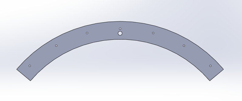
We used the Eagle PCB design to draw the circuit schematics. For the board layout we used the file import-dxf-1_6.ulp from https://github.com/erikwilson/import-dxf to import .dxf file from earlier on which determines the shape of the circuit board. ULP refers to user language programming. It is like a script which is executed by Eagle. To run the file simply in board editor select File-> Run ULP. For this particular .ulp we found that the import only works with a metric setting. After that was done we continue with routing the board.

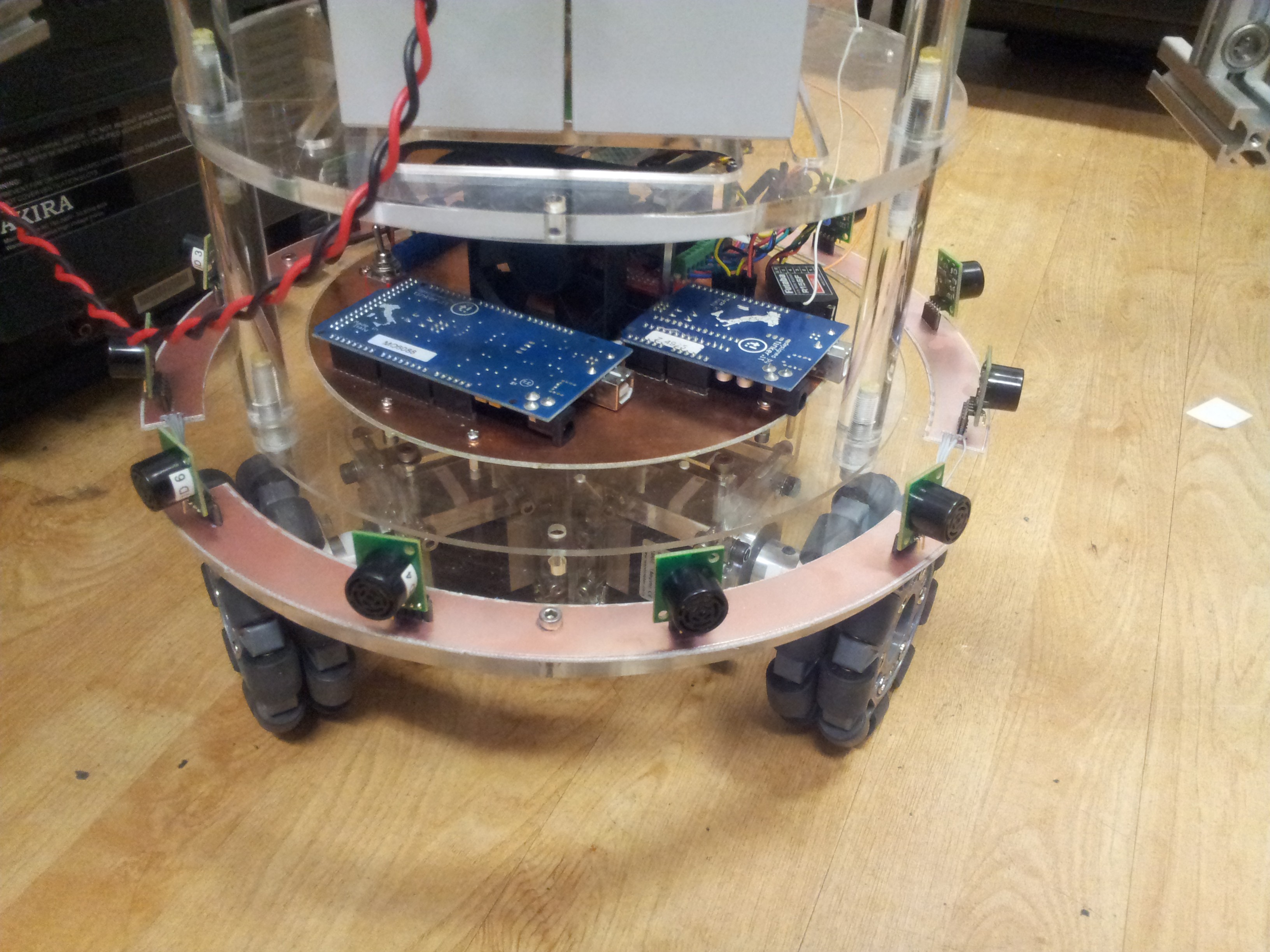
The final board design was then routed out. After populating with a number of headers and loads of botching to connect the ground planes. Finally the boards were connected together and installed.
Now we are in the process of testing the sensor array. First indication was that by taking measurement consecutively, there was some amount of crosstalk between the senors, i.e. pulse from one sensor is received by another. We would need to change the measurement sequence and massage the output so that it is compatible with a certain type of ROS sensor topic.
Discussions
Become a Hackaday.io Member
Create an account to leave a comment. Already have an account? Log In.