Close
0%
0%

Exodurans

Like Arduino, but made for demanding environments, e.g. Space.

Similar projects worth following
µC -s are easy to fabricate. Colorful communities thrive around particular platforms. Mass produced µC -s are ubiquitous.

In fact they are so ubiquitous, that people are trying to push their envelops. Take for example the Ardusat Project (https://www.kickstarter.com/projects/575960623/ardusat-your-arduino-experiment-in-space) - they want to put an Arduino in Space.

Arduino is not designed for this. Ardusat does not come with a space radiation shielding. However, the project mentions multiple Arduinos running parallely and voting to get rid of the error (http://hackaday.com/2012/06/15/ardusat-puts-arduino-experiments-in-space/) - I personally am not impressed. See here : http://www.dsl

Project Goals

  • Modular System
    • Supports Daisy Chaining and Neural Netwrok / Swarm Behavior , regardless of communication method used.
    • Aware of neighbors / partners
    • Endures demaning Environments
    • Supports wide range of mission profiles

    Mentioning a list of goals is rather simple. Realization is a different story.

    Example Mission Profile

    I will take the example of a set of 3U Cubesat.

    The cubesats will be placed at an altitude of 200 Km, with a mission duration of 20 days - a typical time frame of observation necessary after a natural disaster, for example (Note : currently such observvation periods refer to land / air based observations - usually people don't launch specific short duration missions to monitor aftermaths of disasters ).

    The Exodurance system will serve as the Central Nervous System of each sat. At predetermined times (ignoringg orbit anomalies) a cubesat will come in anothers view, and then they will broadcast a fault tolerant message to each other. This message will use high level grammar, so that the communication error is minimal. The message will also contain information about the sender cubesat. The reciepant, upon reception will decode the info, and may decide to raise a self reconfiguration signal. this part will be done by a µC.

    The reconfiguration signal will be used to change the values stored at a register, which in turn can be read by an FPGA. The FPGA is also reading the output of a horizon looking color intensity meter and a camera - and feeding the transmitter. The change of configuration register value can be relfected in the change of filters used by the color intensity meter - or to reject part of the camera input - which may contain errors.


    Name
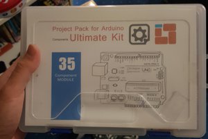
    The name Is inspired from Deinococcus Radiodurans, whose picture (courtsey : Wikipedia) is used as the project pic. The name means Exotic Endurer.

    Status
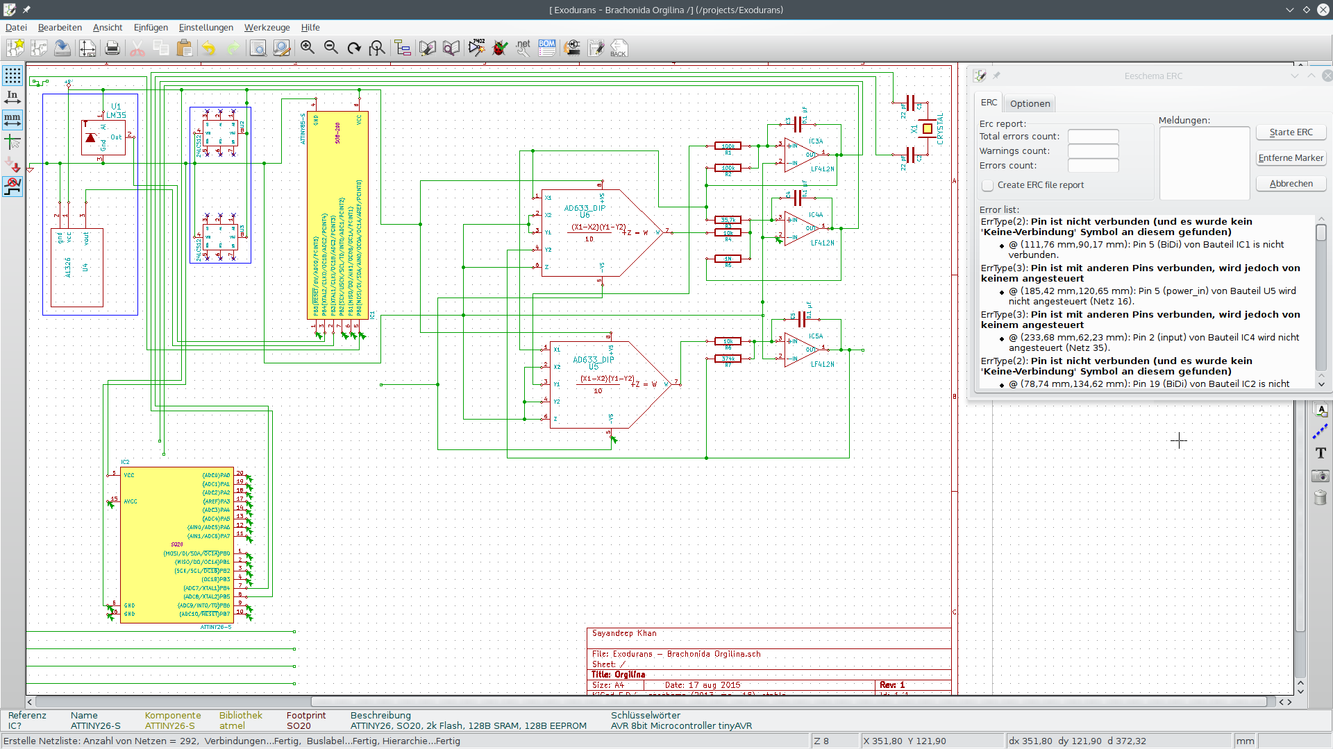
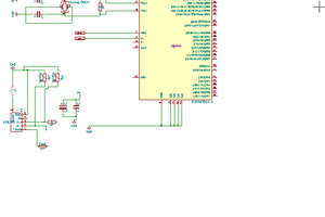
    Developing the very first board : Brachonida Orgilina .

    Board shall withstand Atmospheric Flights up to 60 km, sustained for 60 minutes.

    • Development with KiCad

      Sean S Con08/17/2015 at 06:24 0 comments

      A picture speaks more than a thousand words .


      The Brachonida Orgilina Board (UNDER DEVELOPMENT using KiCad), Contains 20 MHz on board crystal, a Chaos Generator, on board stray electric field detector (Hall Sensor - still have to find a suitble amp for it.) and on board temperature sensor, as well as two 512kb EEPROMS for live reprogramming of device.

    • Project Launched

      Sean S Con08/17/2015 at 06:17 0 comments

      The project Exodurance is officially launched.

      I will make a proper webpage , an youtube channel, and a github repo. Stay tuned.

    View all 2 project logs

    • 1
      Step 1

      Do your homework.

      The first thing to keep in mind are the proximity effects. If you have conductors parallel to each other, carrying time varying signals, they will induce a time varying magnetc field on each other, which will induce a voltage in both - this stray voltage is not wanted.

      Read for example http://www.solidodesign.com/uploads/1_drennan_cicc06_v3f.pdf - This does not really talk about things in an easy DIY manner, but it helps to read it.

      Then you might want to read the rules of thumbs for keeping wires away from each other - such that they are not influenced by each other . Make sure that you read the relevant documents, such as this .

      As a rule of thumb : Twist wires that carry signal in different directions at the same time together to minimize this.

      Secondly, each pair of conductor in the Universe has some capacitance between them. Dealing with it is a bit more complex than the previous point.

      Here is a good document to prepare for PCB design issues.

    View all instructions

    Enjoy this project?

    Share

    Discussions

    Similar Projects

    Does this project spark your interest?

    Become a member to follow this project and never miss any updates