 scubabear
I've made hundreds of circuit boards over the past 27 years for electronics special effects movies over the years, so I figured I probably had something that would work. I wanted essentially a timer with a MOSFET to switch 12V through PWM. I had recently finished something for a movie coming out later in 2015 and I had a bunch of PCBs left over form it, and I realized I could use one of these little boards with almost no modification.
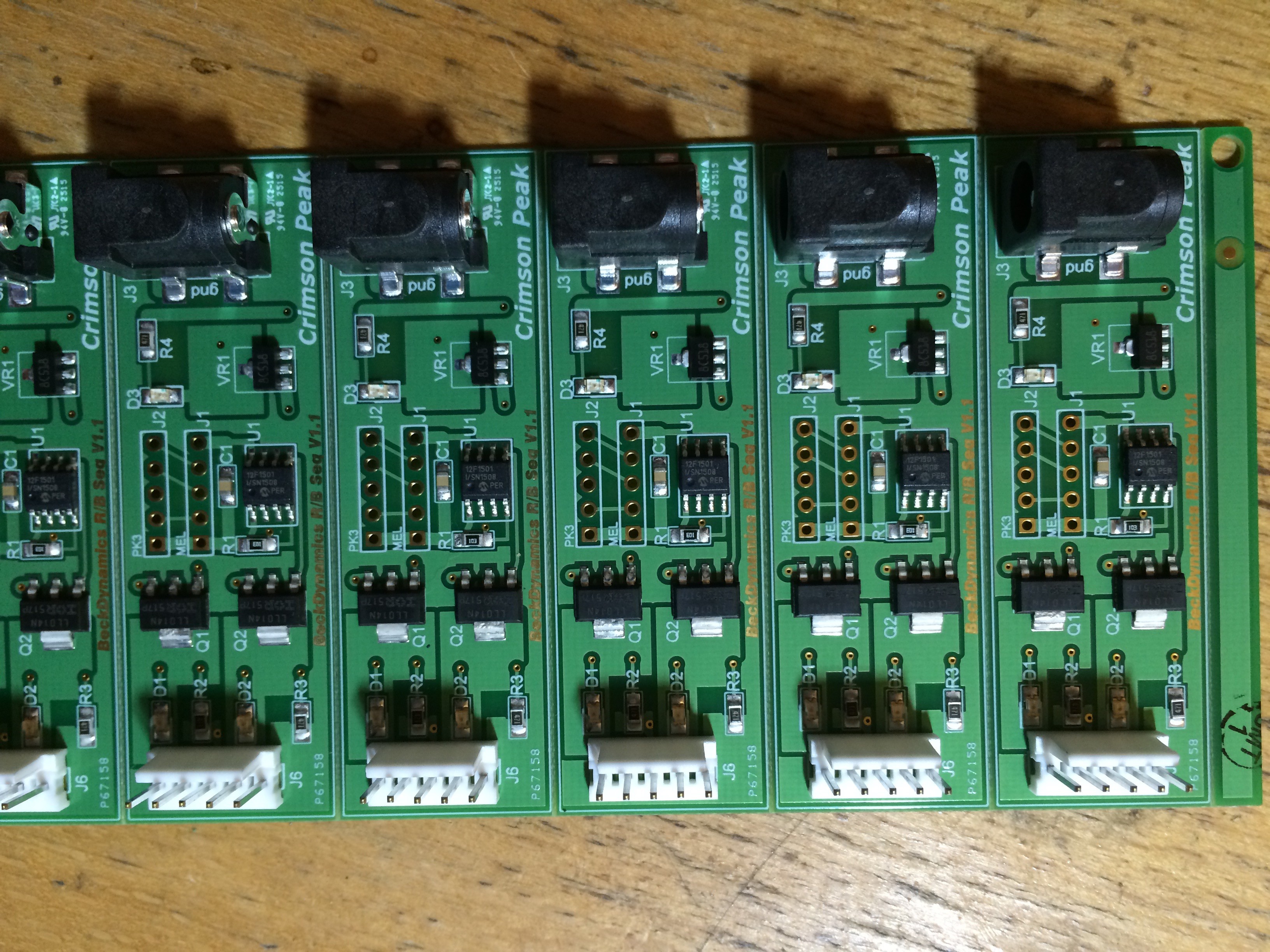
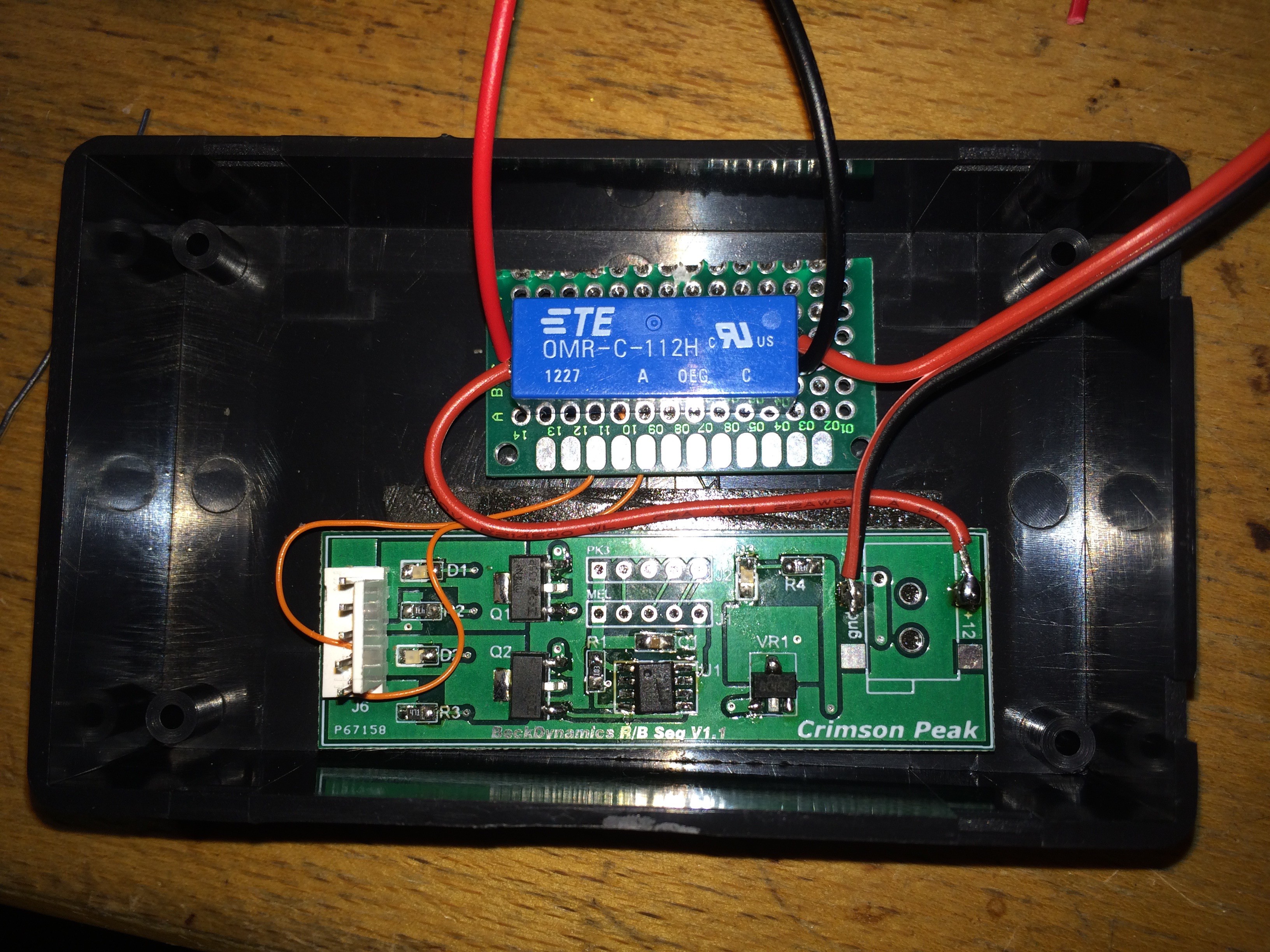
This board has two MOSFET outputs for two different LED control channels. One of my design goals for this was to have the battery last as long as possible without recharging, but since I was using 12V LED strip and a 5V PIC processor, sleeping the processor wouldn't be good enough as the 5V regulator would always draw some current.
The solution I came up with was to use one output for the LED tape, and use the other output to switch a relay to open the circuit from the battery pack completely. Then all the pushbutton switch would have to do is close the circuit across the relay contact--the µC would activate, turn on the relay coil, and then the pushbutton switch could be released. The µC would fade up the LEDs, time their on duration, fade the LEDs off, and then turn off the relay coil to save the battery. This approach worked really well, and the reed relay coil only draws a mere 11mA.
Discussions
Become a Hackaday.io Member
Create an account to leave a comment. Already have an account? Log In.