 novirium
The electrical connection and bus between the modules is a big part of what would make the InterBand standard successfull. The current plan involves 5 connections: GND, 3.3V, SDA, SCL, and INT. GND and 3.3V are pretty self explanitory, and SDA and SCL essentially implement I2C or TWI. Even though these protocols support multiple hosts, the intention behind InterBand is to have a single host module with many slaves.
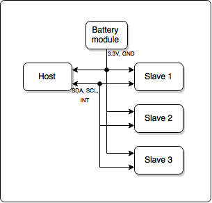 This host module would generally be the communication interface with the outside world, whether that is a simple Bluetooth connection or a more complex display interface. The INT line is my attempt to try and support low power features in supported modules. The idea here is that unless a module is actively doing something, it can enable any low-power modes it supports, and wake up when the INT line is asserted. Any module can assert the line, and when it is pulled low all modules must wake up. If it was the host that asserted INT, it then does what it needs to (communicating with a slave module), before letting the line go. If the host wakes up due to a slave asserting the line, it polls them, finding who is asserting it and sorting out what it needs. This scheme should allow very basic modules to be made of ICs that natively support I2C or TWI, but also add a bit more flexibility for those with a microcontroller on board.
Actually getting these 5 circuits connected between the modules is another problem entirely. There are several requirements of such a connection: First, it must be flexible, as in able to flex over the hinge between modules. Sharp, acute angles aren't necessary, but the physical hinge should limit movement before the flexible connection is damaged. Second, it must be rotationally symmetric (as must the physical hinge).
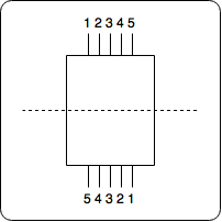
By this, I mean that both ends can happily connect to the same end of another module (no distinction between "leading" or "trailing" ends). This is to avoid putting limitations on the configuration of modules in the band - individual modules may be designed to work with a particular orientation with respect to the wrist or arm, and as long as they have an inside edge (which would normally be slightly concave to curve around the wrist or arm), they will be able to connect to other modules in both orientations. The third requirement is that the connection is a removable, re attachable part. Modules should be able to be mixed around in the band with relative ease, and a soldered connection between them kind of prohibits this.
Flexible, easily removable electrical connections are hard. My first thought regarding this was to use some sort of pogo pins, with a conductive target pad on the other side of the hinge, but even a cursory amount of thought down that path revealed that the sliding connection as the hinge flexed could momentarily interrupt the connection - not good for a high speed bus. Additionally, dust and other foreign particles would be free to get in the way and obstruct the connection.
The next idea was standard flex cable jumpers. These seem to be readily available and the connectors that the ribbon is inserted into are quite compact, but so far I have been unable to find any shorter than 25mm (to not intrude too much on the space in the modules this really needs to be under 15mm or so). The right-angle insertion nature of these connectors also isn't ideal, as they would need to be inserted in sideways while the hinge is slid into place, complicating attachment process.
The leading solution at the moment is to use custom flexible jumper strips, with a low profile stacking connector at each end. This has the advantage of being attached from the inside of the band, rather than tangentially. The connectors themselves are readily available, and I'm currently looking at these, though they're not exactly cheap. There are two ways these jumpers could be constructed, either FPC (more expensive), or two thin PCBs with a soldered cable (cheaper, less compact).
Discussions
Become a Hackaday.io Member
Create an account to leave a comment. Already have an account? Log In.