 Patrick Van Oosterwijck
LiFePO4 is a battery technology that finds wide application in power tools and electric vehicles. It is an inherently stable chemistry (which makes it safe), is environmentally friendly (no heavy metals), has very high power density and many more recharge cycles than other Lithiums.
It also has a perfect voltage range for use with electronics: 2 - 3.6V. This means most modern chips can be powered without the use of a voltage regulator, which tends to be a big power waster in low power systems.
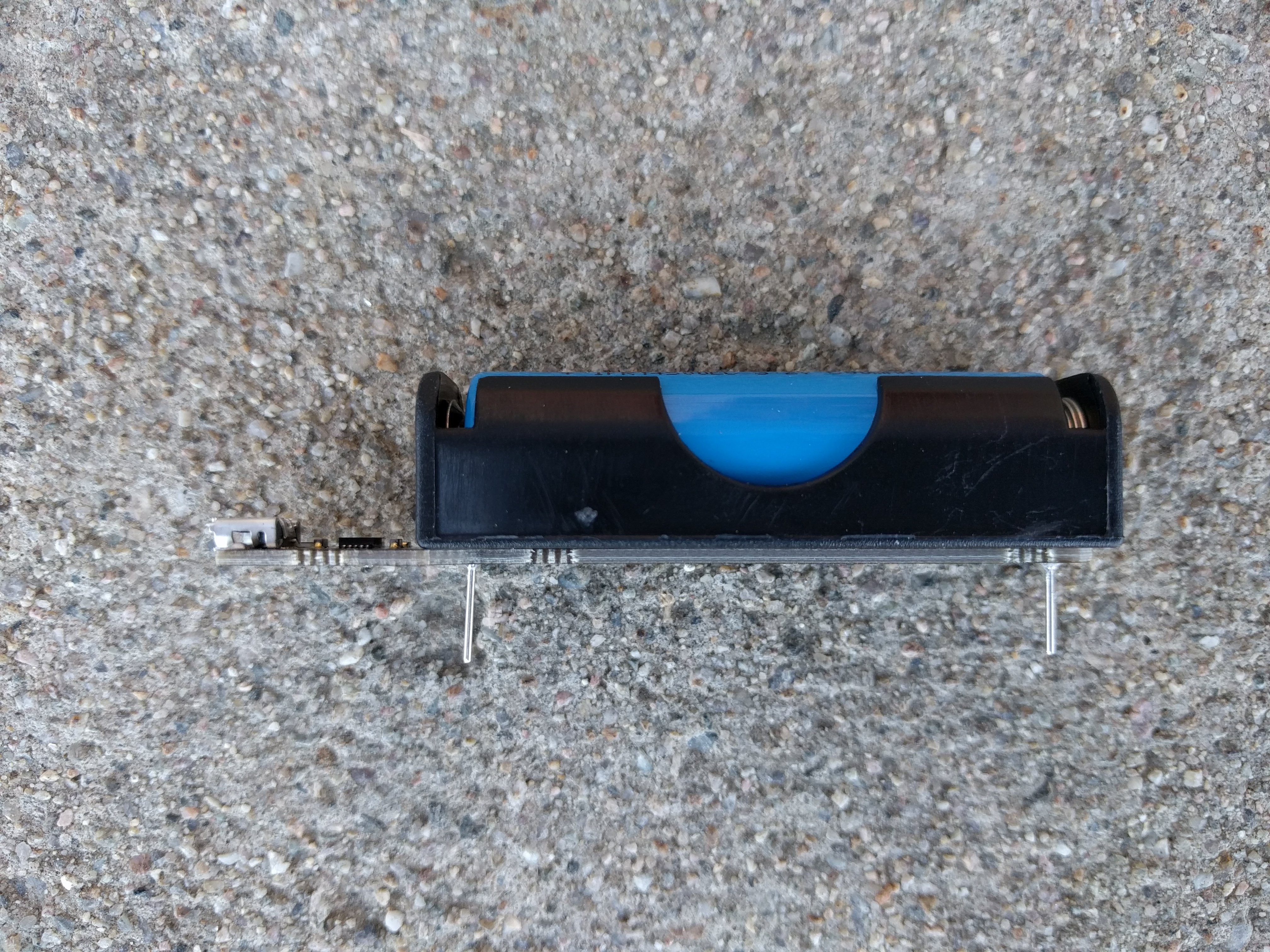
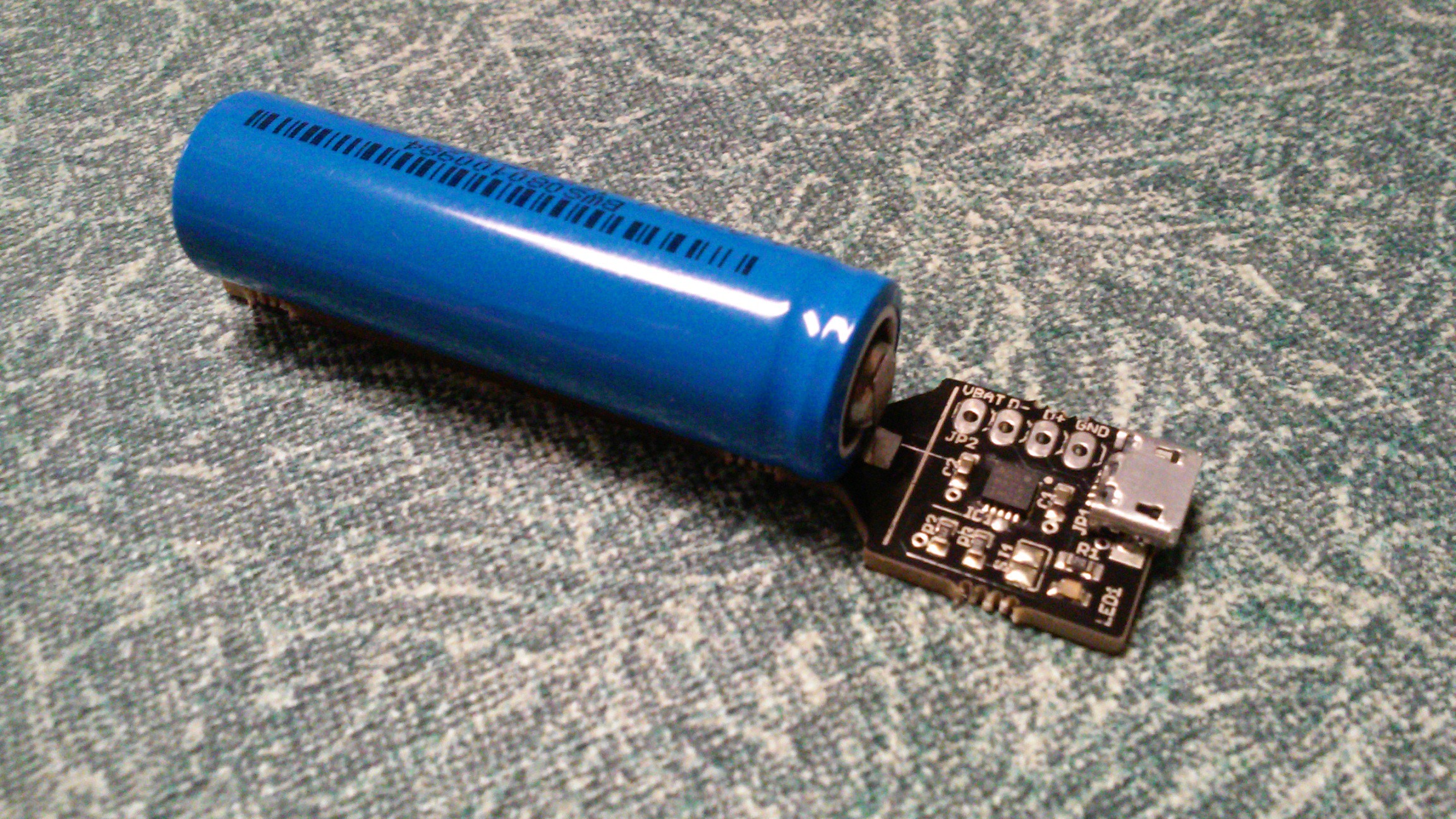
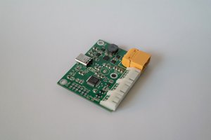
So here is an easy to use module to get started with LiFePO4 in your own designs. It's basically a battery with an integrated USB charger. All connections are on a 0.1" grid for easy integration. Take power straight off the battery holder terminals, or if that doesn't fit in your design, cut off the battery terminals and connect to the 0.1" header footprint.
So stop using old lithium cells that require a voltage regulator and last only a couple hundred cycles, and upgrade to the next level with LiFePO4!


 Alex Klimaj
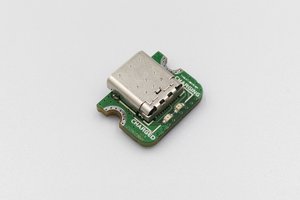
 Beast Devices
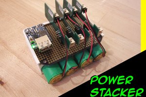
 isaacporras
 davedarko
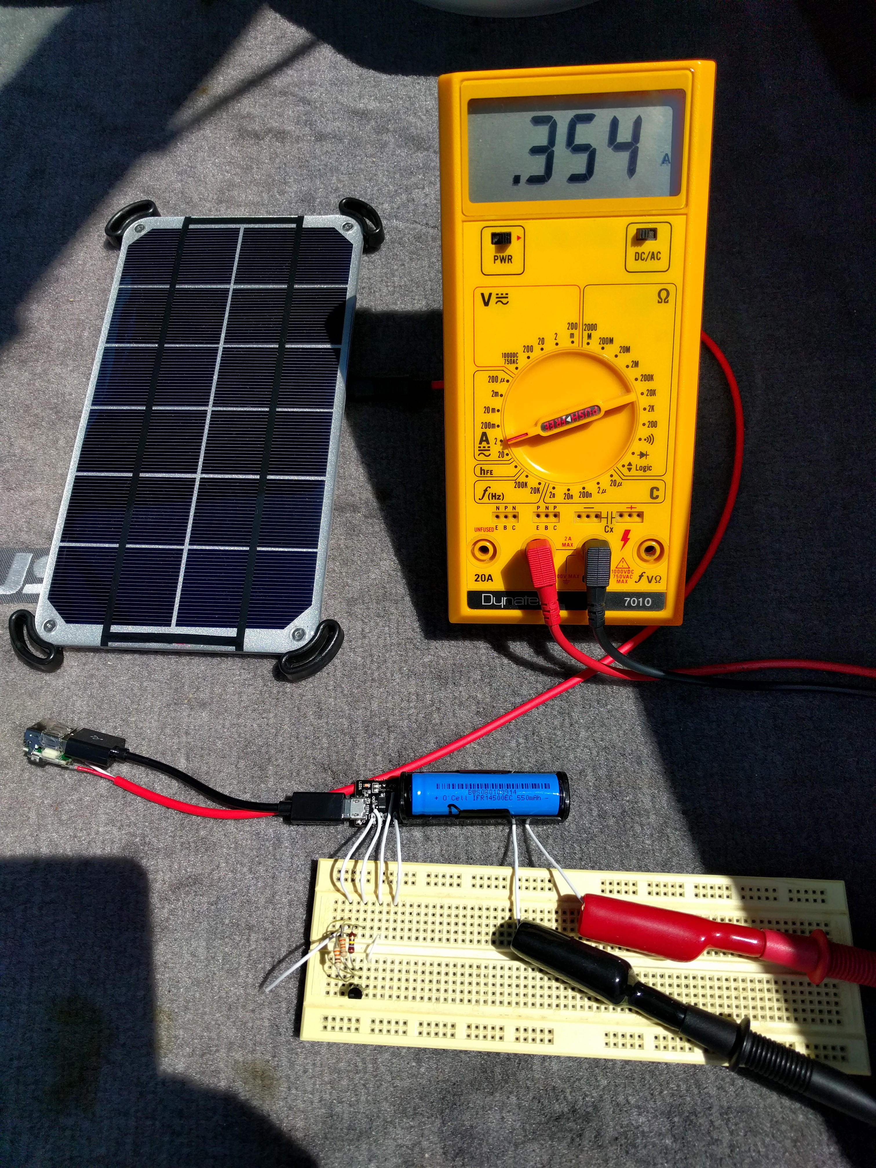
Something I don't quite understand from either this project or the MCP73123 datasheet: It says the maximum regulated output voltage is 3.618V. It also mentions 0.5% tolerance. So that means a maximum of 3.7989V. If you have the load (ie. your project) connected while charging which I'm assuming most would want to do, that means that whatever 3.3V part you're powering will see that voltage, right? And every 3.3V part's datasheet I've seen says absolute maximum 3.6V.
How do you deal with this or is this just not a problem?