 Hooptie J
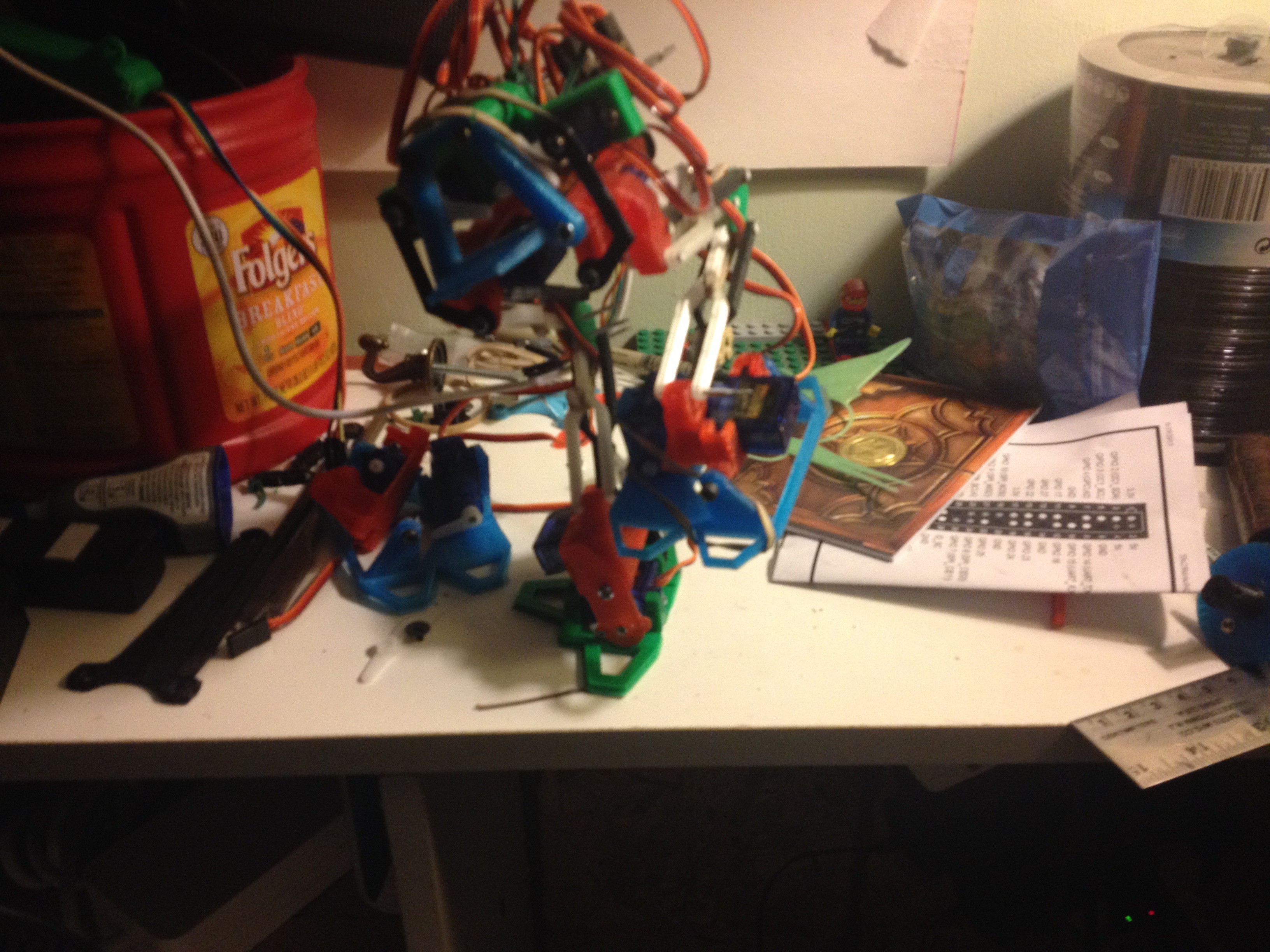
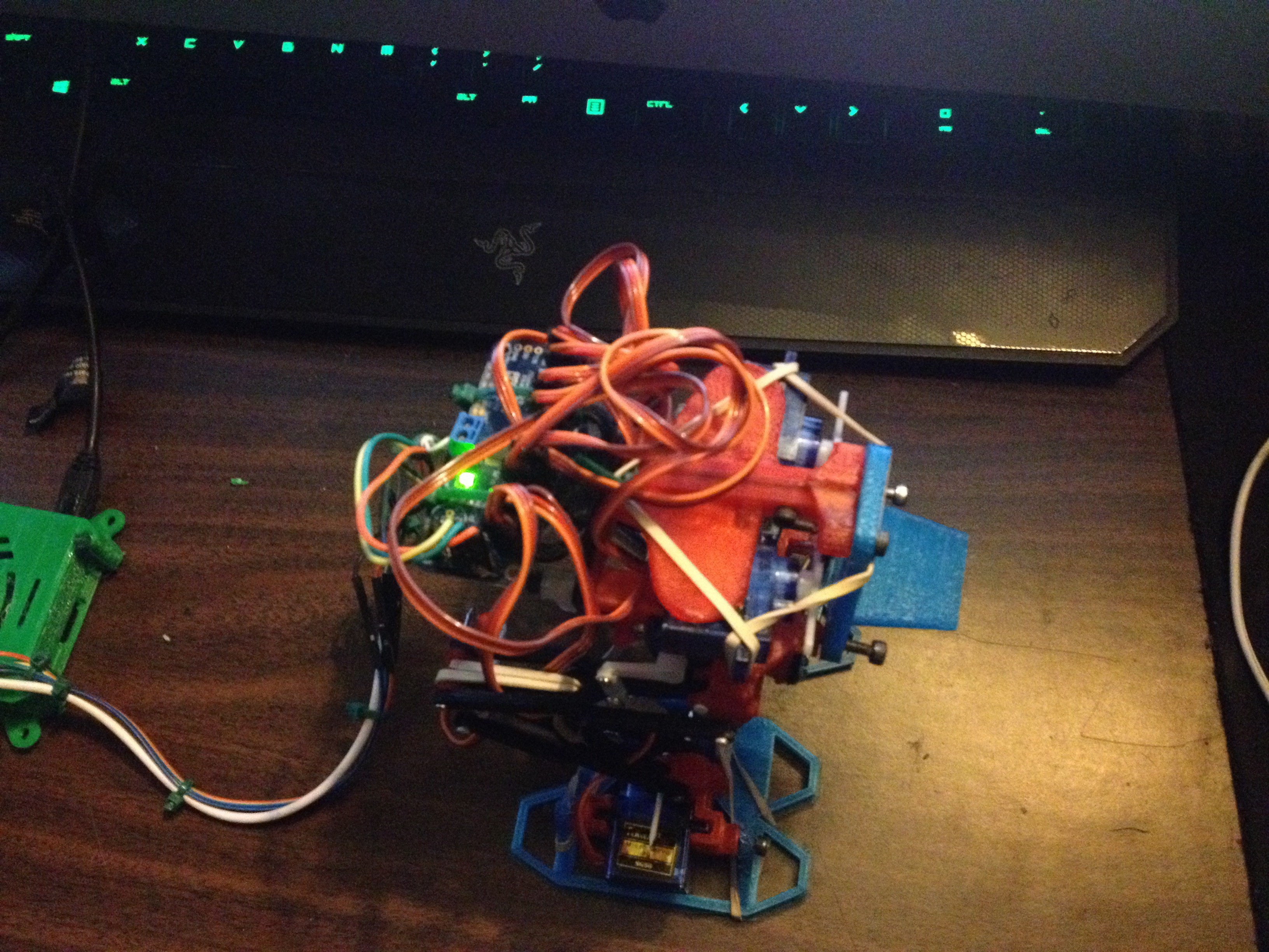
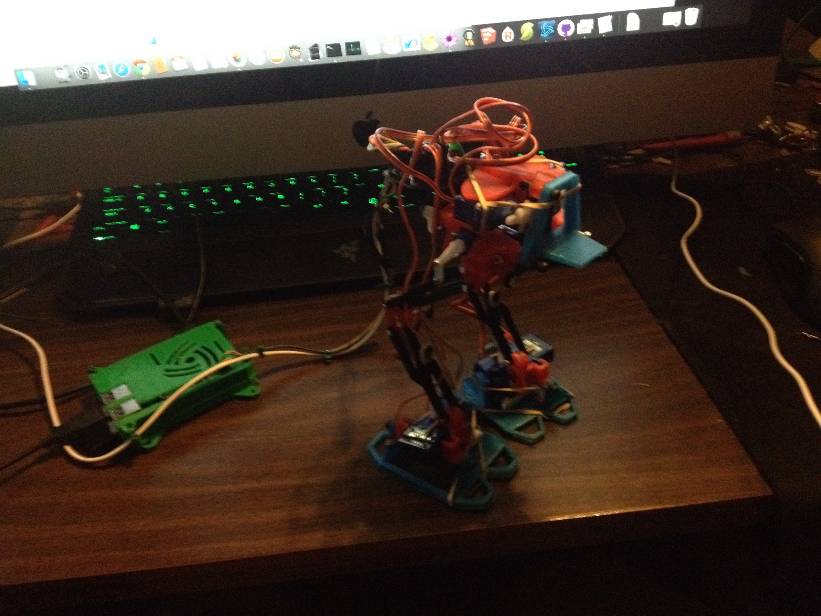
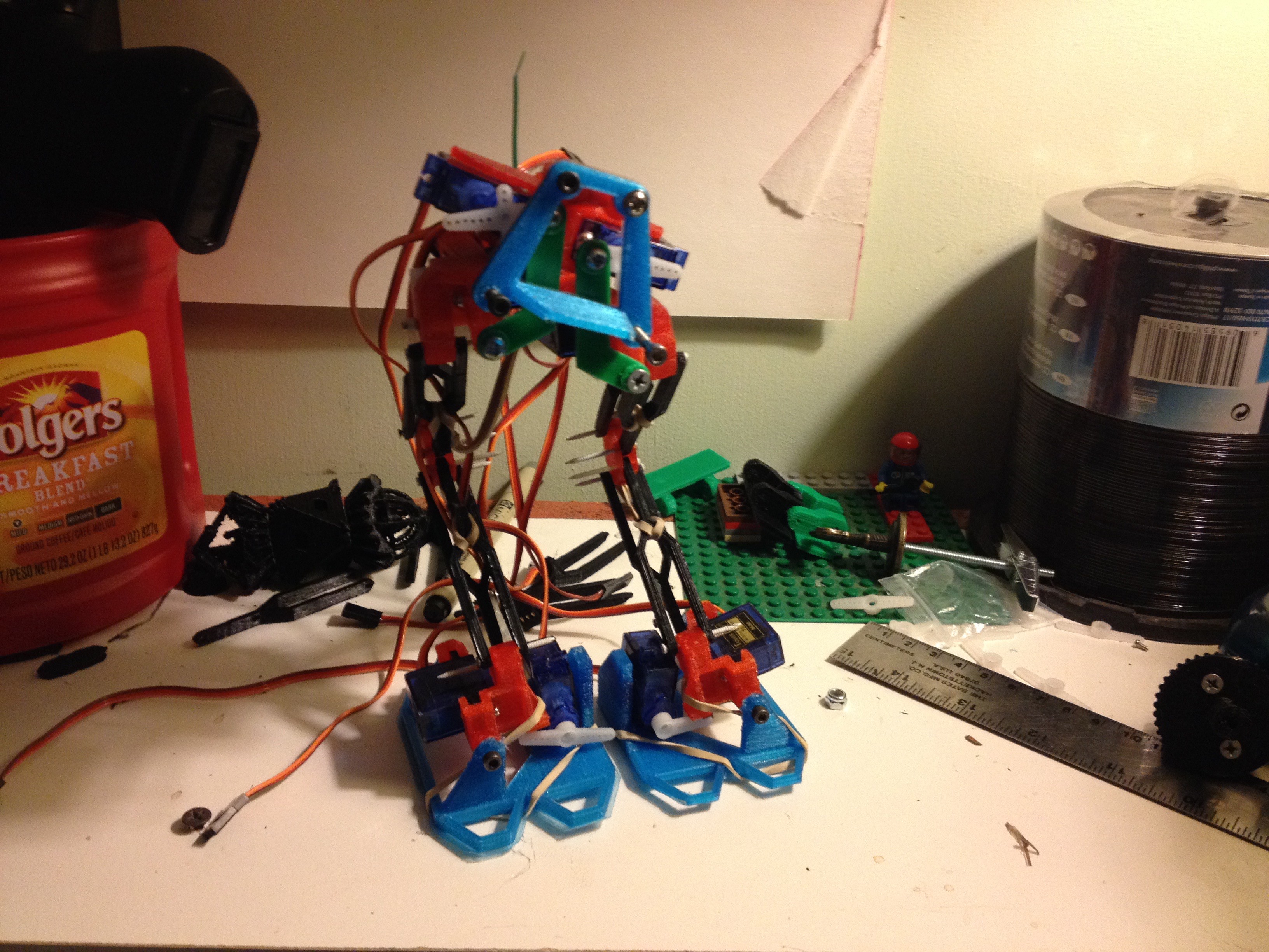
Mk 3 is an Original Design 8 DOF Biped "Chicken" Walker using tensioned parallel bar legs.
All parts Easily Printable without supports
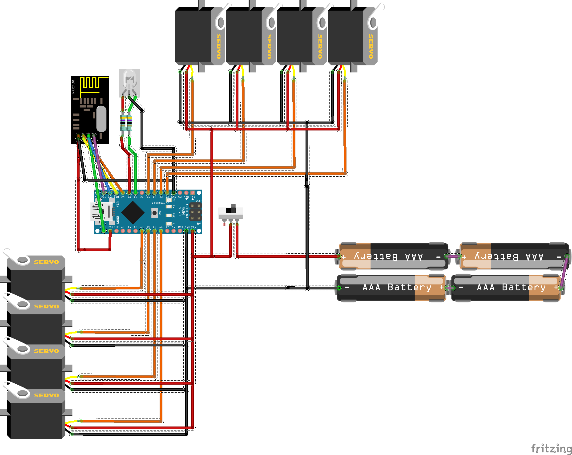
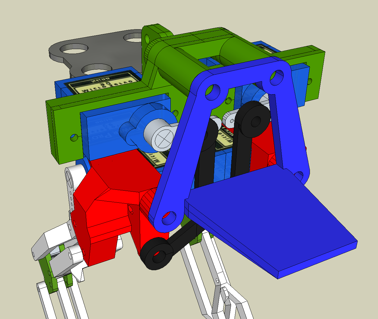
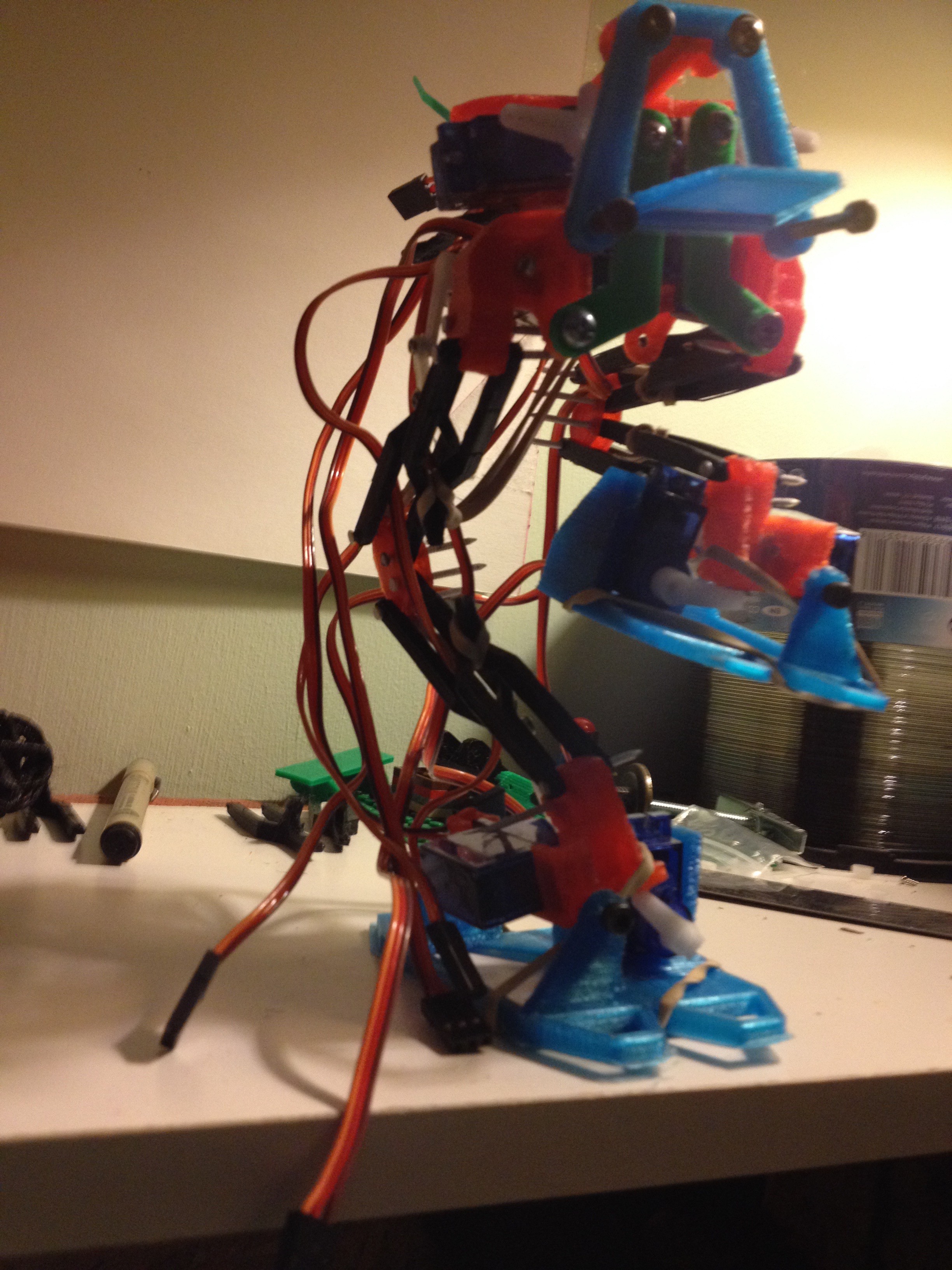
8x Tower microservos, 2 for each ankle and hip, knee actuated by long lever dually by hip and ankle.
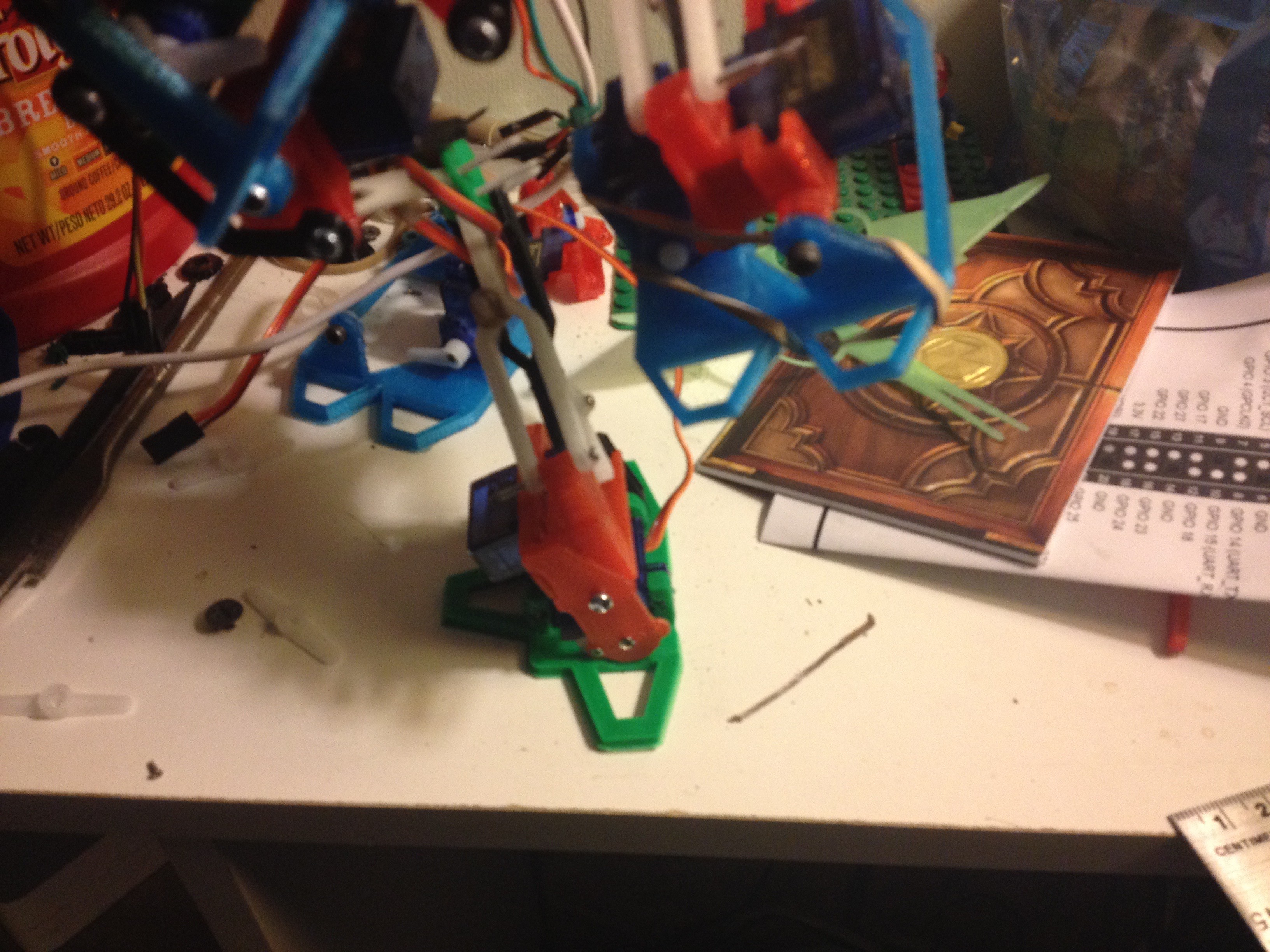
The majority of the weight is supported by a plain rubber band tensioned across the back of the "knees", its just enough force that the servos can both lift the bot, and still lift the opposing foot.
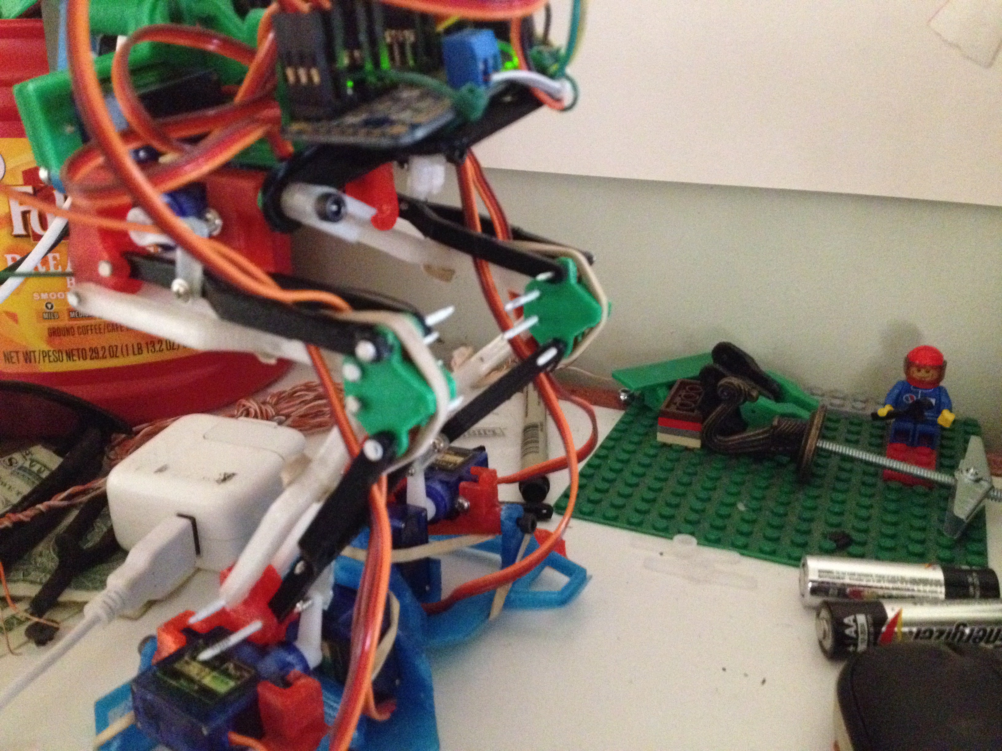
Uses only standard "garage" hardware- M3 and M4 metric hardware, every Home Depot and Harbor freight has this stuff on hand..
Small Finish nails for Joint pivot points- any small nail with a matching drill bit would work.

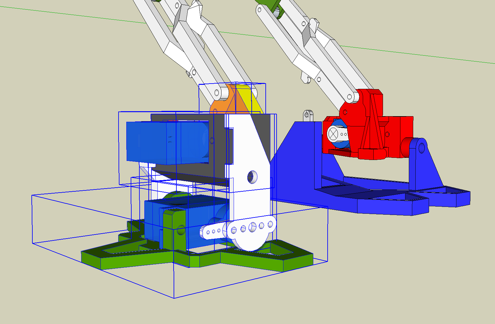
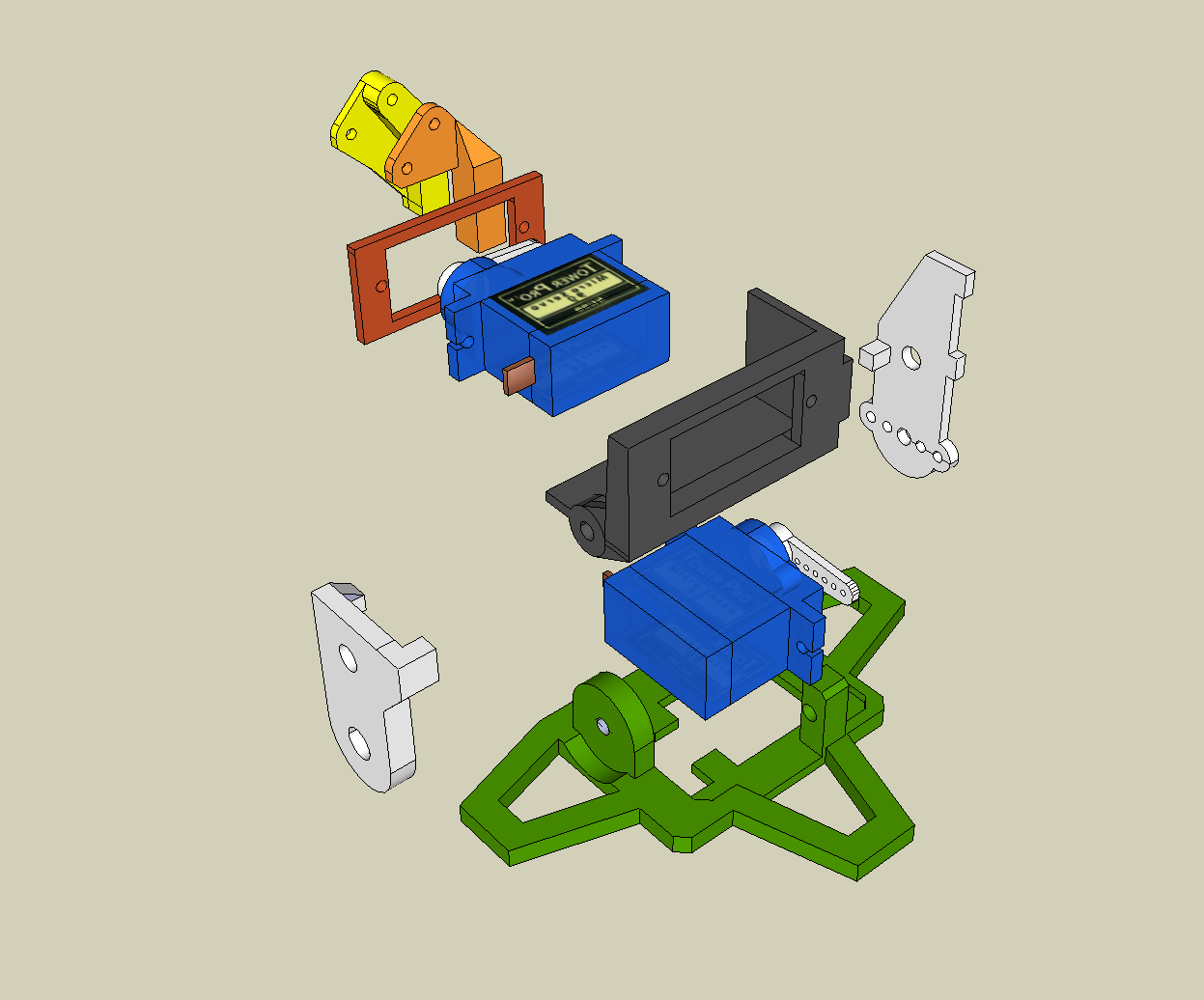
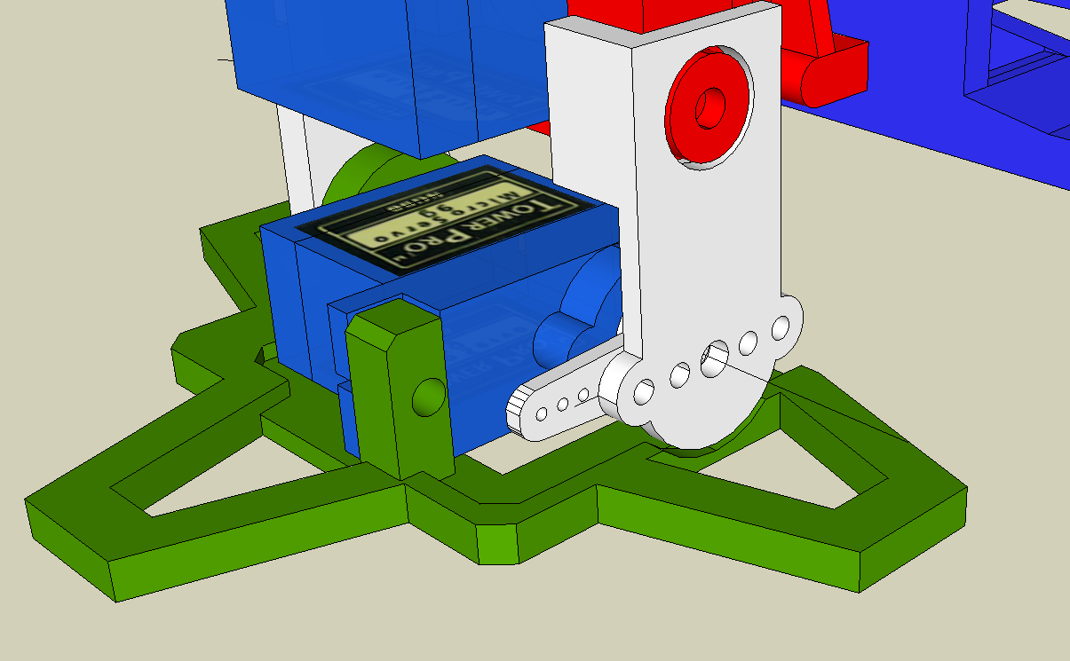
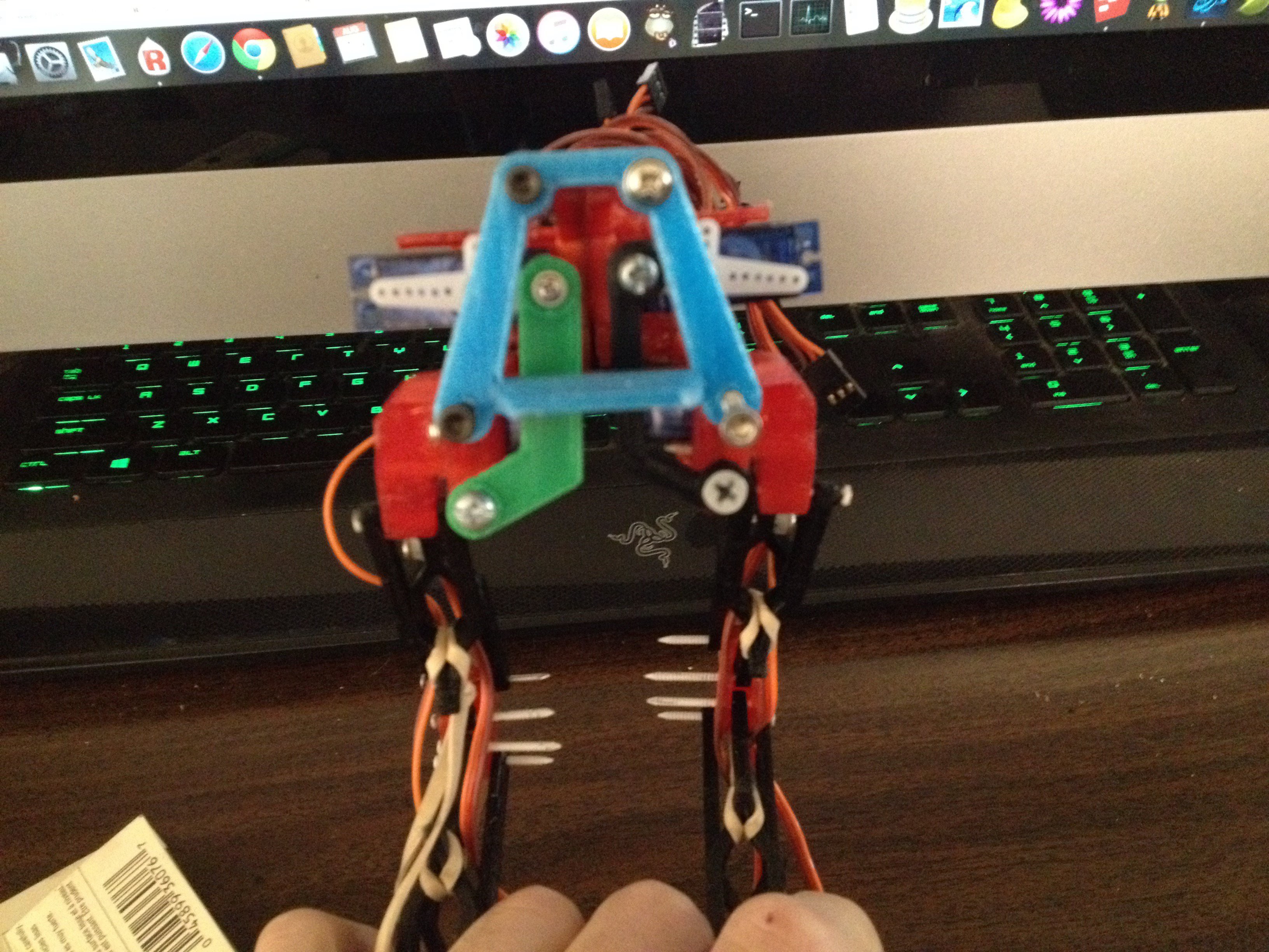
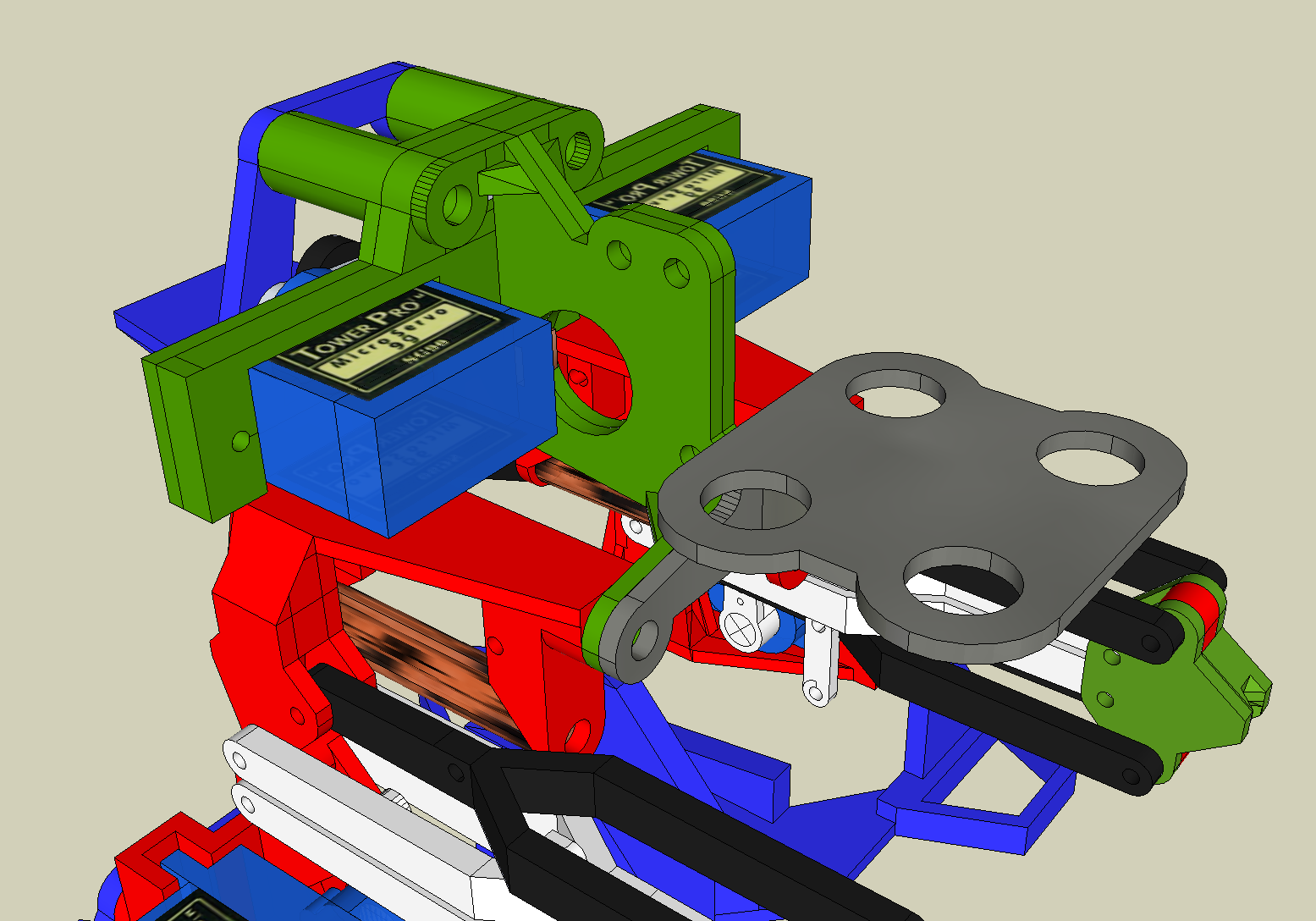 And the part count grows by 2. - from a 2 piece "ribs" to 2 parts for the servo mount, and 2 for the "center" - again , no joke, Anyone who wants to help name the parts are welcome to comment - ive taken to calling this the green section the "ribs"
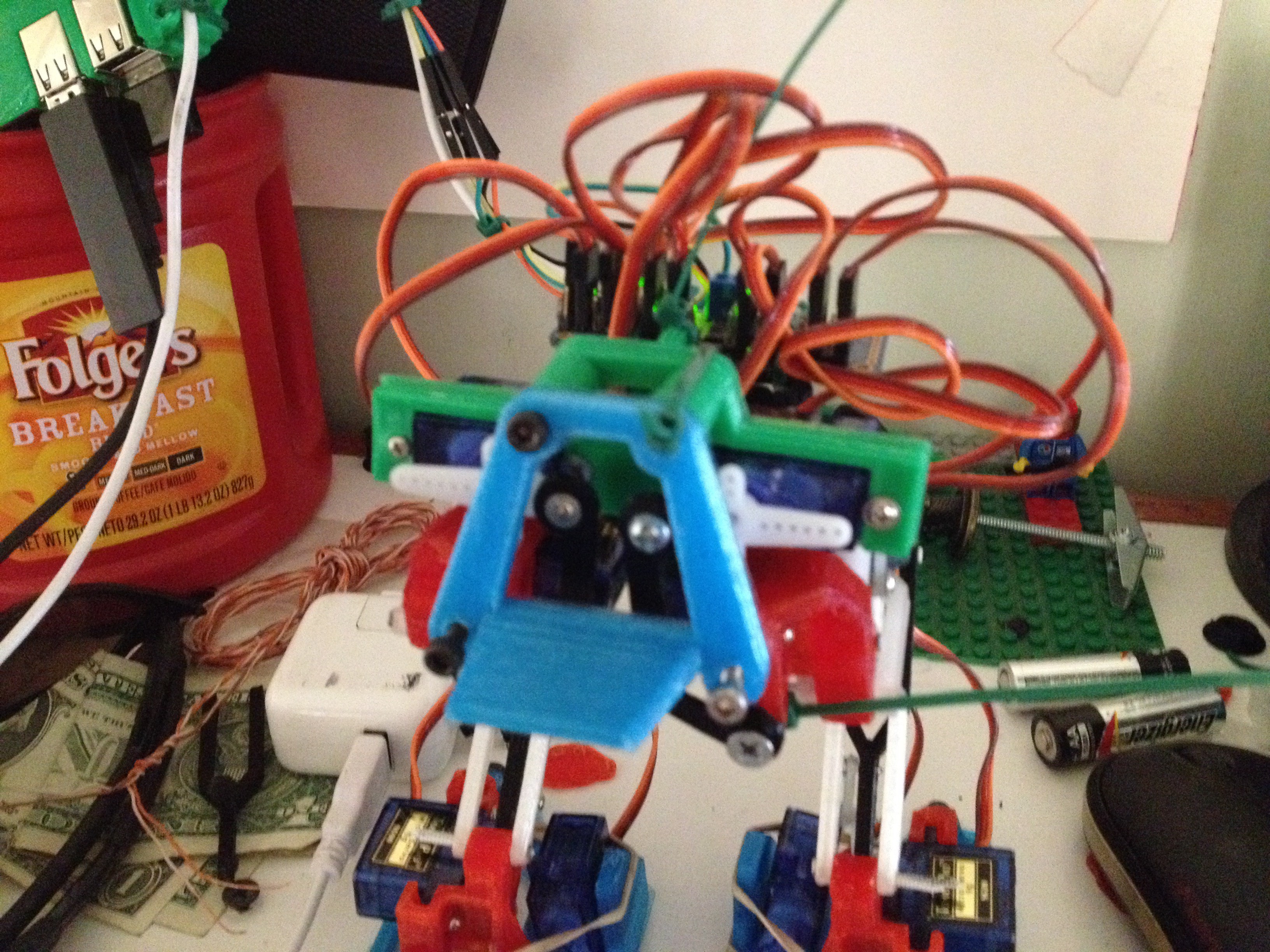
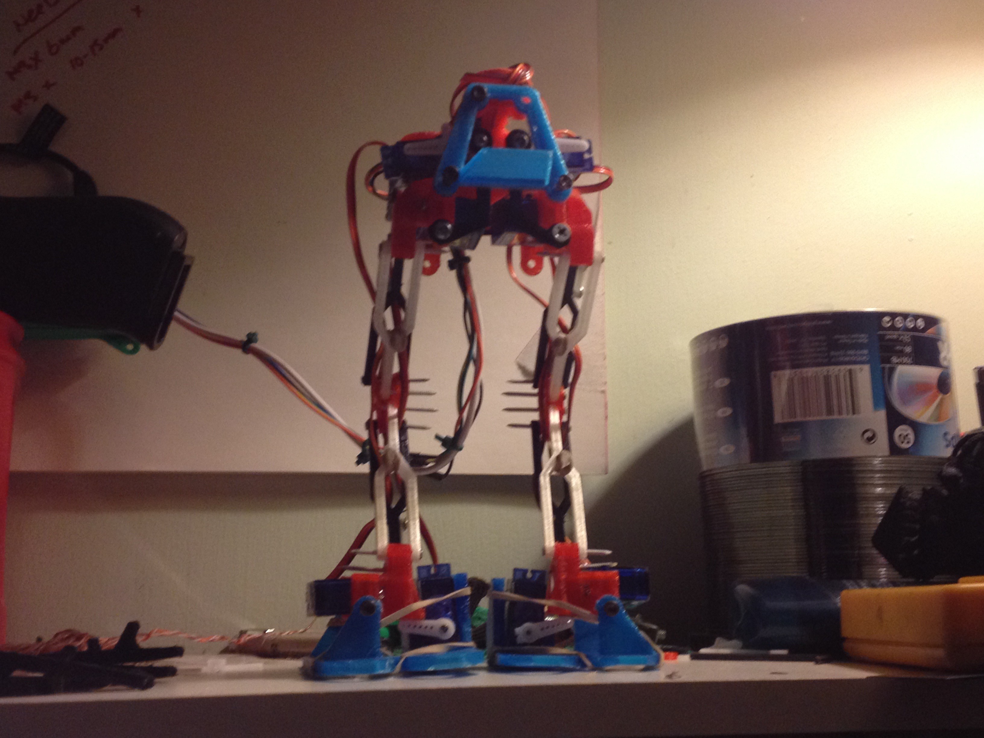
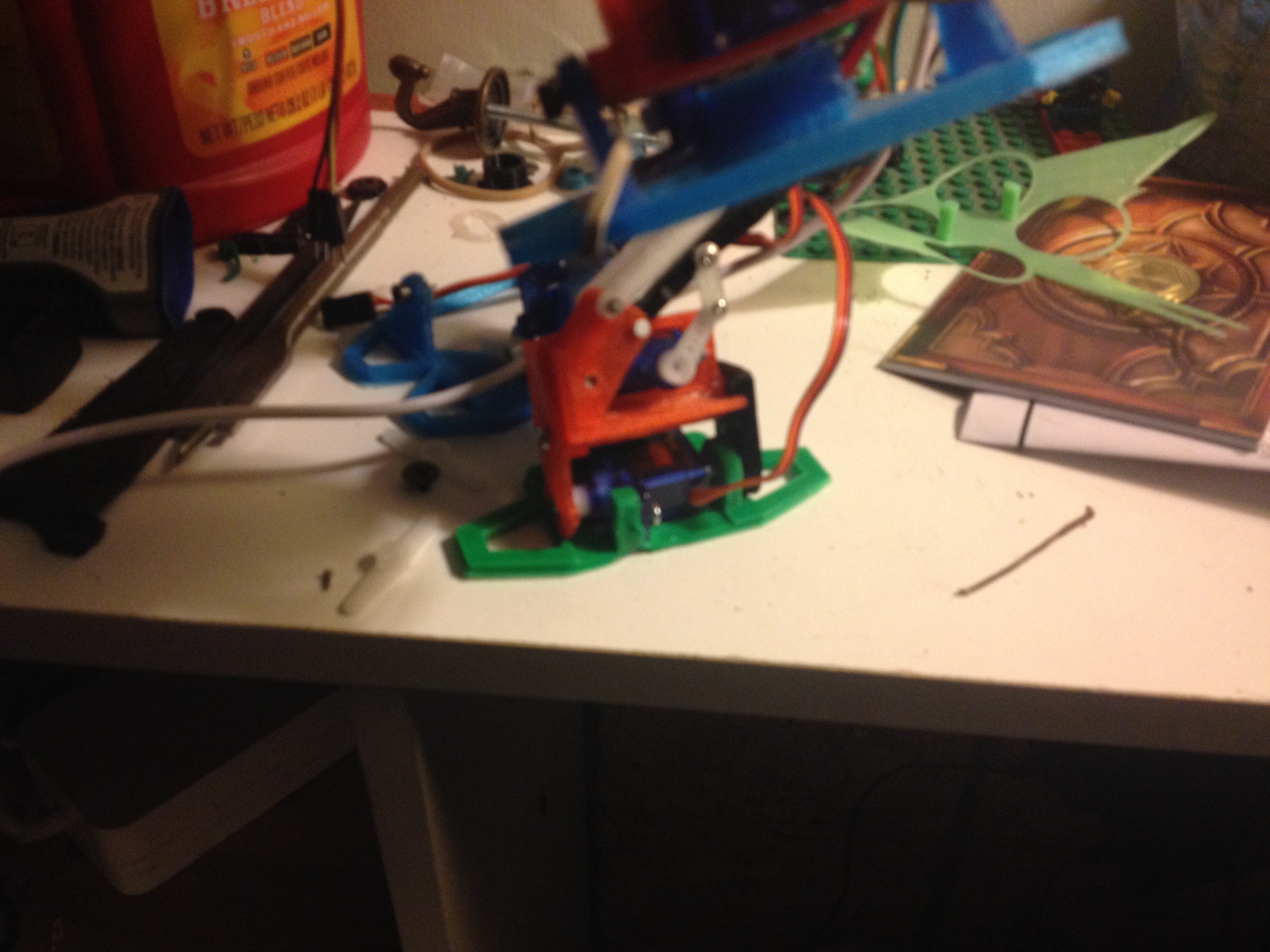
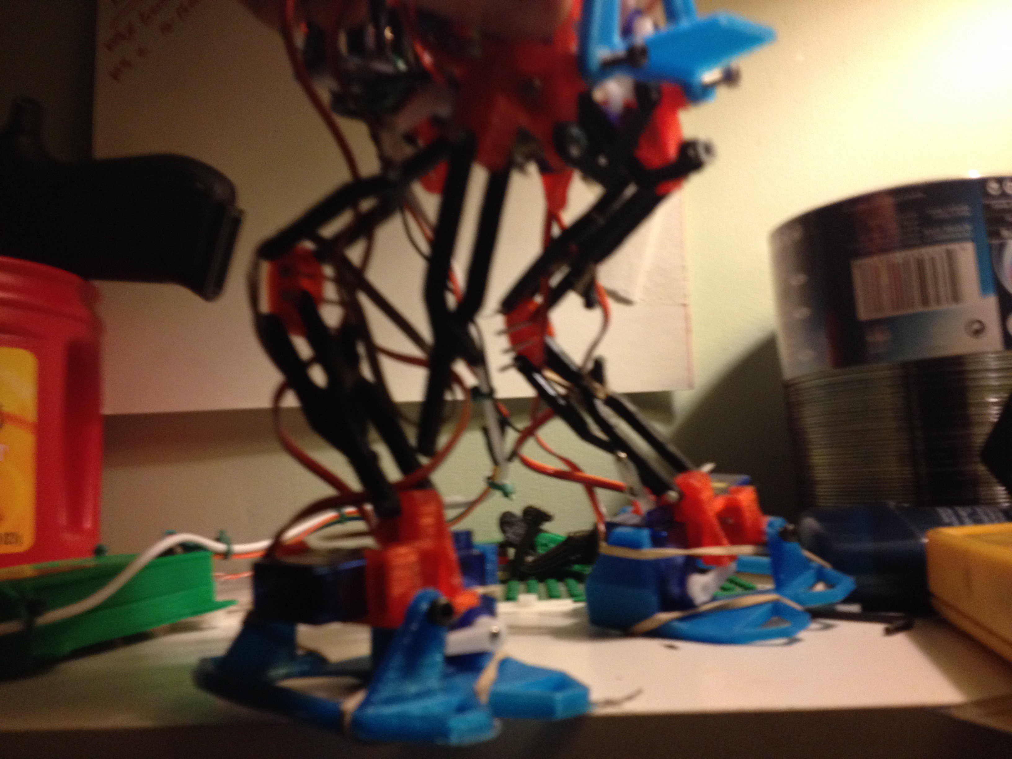 Also, i didnt print any spare leg bones last revision, so this ends Range of motion testing for the day.
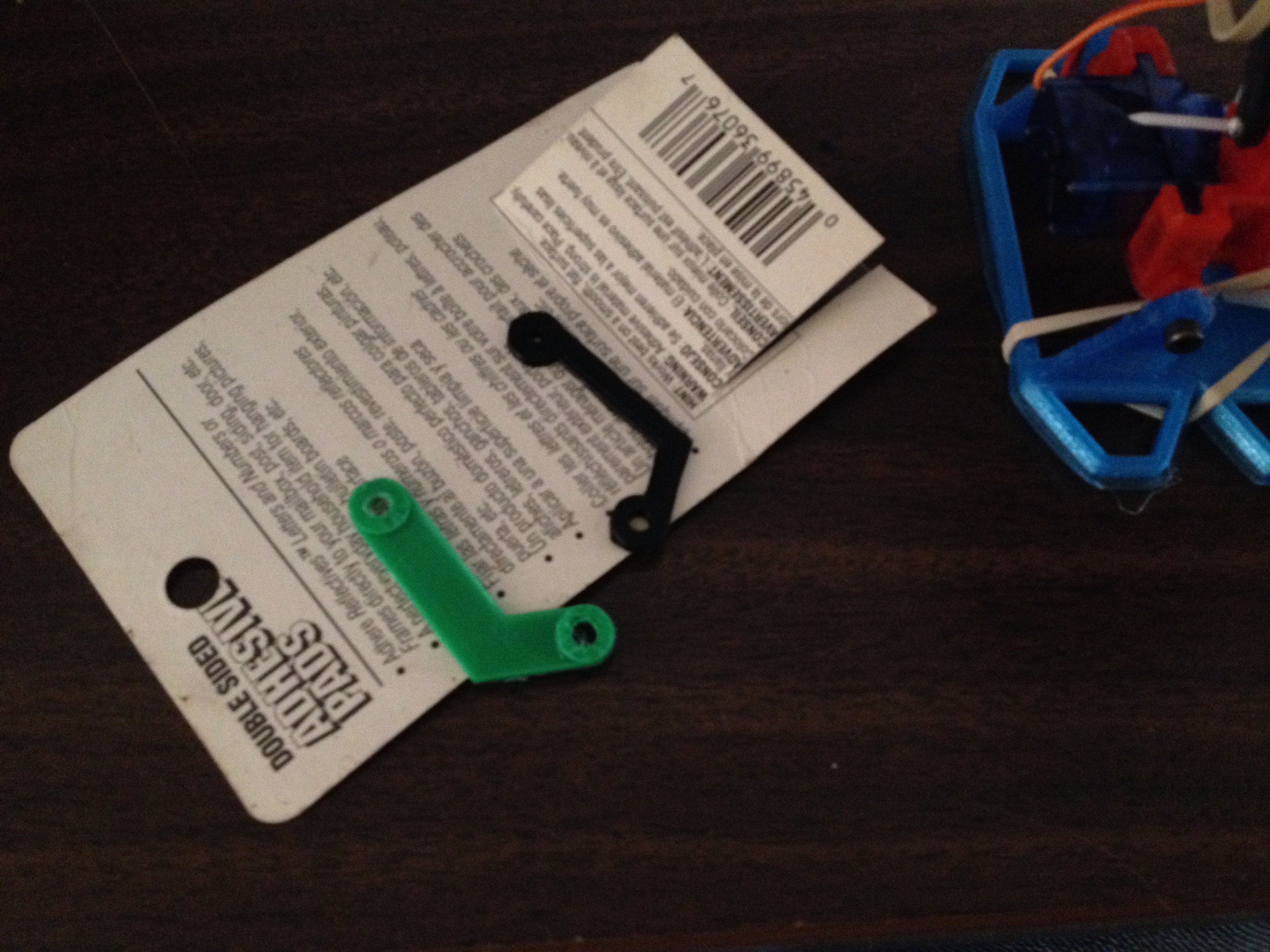


 Martin Vincent Bloedorn
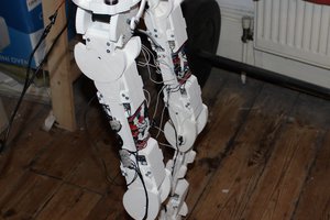
 Dan DWRobotics
 Ranarchy
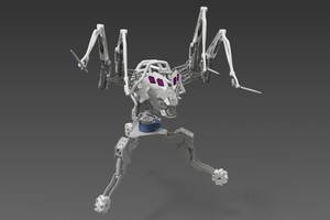
 Val
Val
Since there were no update in a very long time, I'm assuming that this project is shelved or on hold...