-
Breakthrough
05/24/2017 at 03:13 • 0 commentsEdit: the image was wrong, it's fixed now.
One of 3R's Achilles' heel is when dealing with large numbers: efficiency drops linearly... 3R loves small numbers and eats through runs of zeroes but large numbers have looked like an enemy to avoid.
Until today.
The trick is to use additional auxiliary information, which is the range of all the numbers, the maximum value that each one can have. This information is ignored and absent in the classic 3R algorithm but adding it can change the whole behaviour...
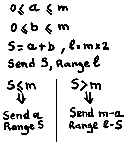
Here is the new algorithm to encode two numbers a and b, knowing their respective limit m:
![]()
This is a crazy breakthrough, compared to sending S then a with range S every time !!!
With this new transform, many things I thought about 3R must be reconsidered...
This "trick" looks like it is somehow linked with "economy codes", and came to my attention while designing a new colorspace for use with 3R... More details are provided in the new dedicated project #σα code.
Nothing comes for free however: the added compaction performance adds a conditional branch (likely to be mispredicted), a comparison, a subtraction, and all of these add a bit of latency for the encoder AND the decoder, which will be a bit slower in FPGA (it's still crazy fast but it might lose 50% of throughput).
-
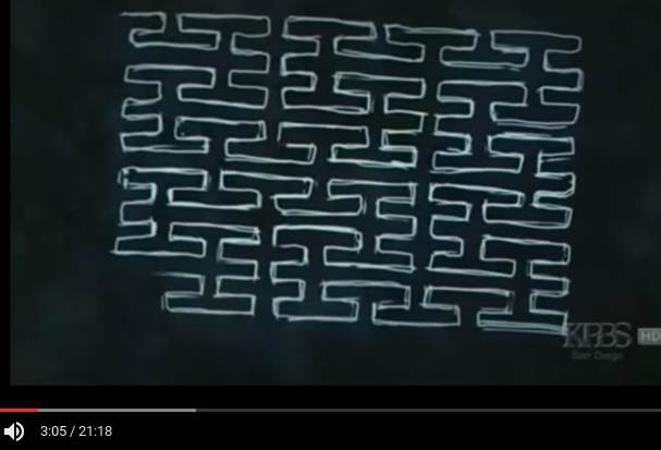
Plane-filling curve
04/16/2017 at 02:41 • 0 comments -
Design of the bit extraction circuit
06/02/2016 at 00:23 • 0 commentsThe "tree walker" circuit is an essential piece of the compaction/compression system but it must interact with another critical element : the circuit that reads the bitstream and expands each value to be presented to the tree walker.
The "vanilla" 3R algo uses a simple bit-extraction system, where an integer number of bits is handled during each cycle. This involves a barrel shifter and some nice logic but it's considered a "classic circuit".
The "enhanced 3R" uses a more complex system called "truncated binary" or "economy codes" or "phase-in code", depending on the sources. This gets more complex because the extracted value must also be compared with a "threshold value" (which must also be computed) to determine if an extra bit is required.
The original version (http://ygdes.com/ddj-3r/ddj-3r_compact.html) suffers from a bad case of bad data organisation, the bits are in an awkward order in the bitstream. When a "long code" is found, one more data bit must be fetched close to the MSB. I'm trying to solve that but it's hard.
I hit a tough problem: I can't find an organisation of the data where less than 2 barrel shifters are required in the critical datapath. I'm not even counting the final MUX to perform the SHR(1).
Going back to the fundamental questions, let's first solve that "original sin" of the wrong bit order. Consecutive bits must be contiguous so a "Big Endian" order is chosen.
Let us now consider the case of a 16-bits "bit accumulator" that contains a 5-bits field. To extract those bits, there are three possible choices :
- The field is aligned/justified to the "left", the MSB of the register:
MSB                                         LSB
15 14 13 12 11 10 09 08 07 06 05 04 03 02 01 00
 4  3  2  1  0  x  x  x  x  x  x  x  x  x  x  x
- The field is aligned/justified to the "right", the LSB of the register:
MSB                                         LSB
15 14 13 12 11 10 09 08 07 06 05 04 03 02 01 00
 x  x  x  x  x  x  x  x  x  x  x  4  3  2  1  0
- The field is not aligned/justified so bits are anywhere in the register:
MSB                                         LSB
15 14 13 12 11 10 09 08 07 06 05 04 03 02 01 00
 x  x  x  4  3  2  1  0  x  x  x  x  x  x  x  x
All of them amount to the same general complexity, number of units and latency.
For example, in all these cases, only 16 bits are represented but the "bit accumulator/Shift register" must actually be 32 bits wide, allowing a new 16-bits word to be added to the register while it is being read at the same time.
- In the "left justified" case, when more than 16 bits are consumed and shifted out, a new 16-bits word must be brought in and shifted (from 0 to 15 bits) before being stored. The justified output must also be shifted (from 0 to 15 bits again) as well.
- Same as 1. (more or less)
- In this case, the input data is written to the shift register in a "double buffering" fashion, one half at a time (alternating MSB and LSB). The complexity is relegated to the read side, where it's not a barrel shifter that is used, but a 32-bits barrel rotator (though with a 16-bits output).
So between one big rotator or two smaller shifters, the choice is not straight-forward. A larger unit needs more fanout and two smaller units can be more easily placed/routed but more units means more control logic too.
.....
Continued at 5. Phase-out encoder/decoder
- The field is aligned/justified to the "left", the MSB of the register:
-
Project status
04/17/2016 at 22:23 • 0 commentsCurrently, only one part of the decoder is developped and available. This is a critical part, the innovative algorithm (which linearizes the tree-walking from the recursive definition) which must be connected to the other blocks.
The other blocks are the bit-shuffler/bitfield extractor, and the output filter (which depends on the application).
Of course, the forward and reverse blocks must be designed so this doubles the efforts again !
Let's just look at the decoder: it receives one block of data encoded as a bitstream (with a granularity of 8 bits so blocks are byte-aligned).
The bitstream is examined and words are extracted from the bitstream: from x bits they are zero-extended (usually to 16 bits).
Those words are fed to the tree-walker unit that select which words to bypass or subtract and store for later. In the end, the output words are smaller.
These smaller words, either a difference or a litteral value, are sent to the reconstruction filter.
The encoder is almost the reverse but needs one more step, so this is not a totally symmetric process, and it requires more buffering, one full block must be stored before being sent.
So far the decoder has been tested with manually generated word streams. They can also be copy-pasted from dynamic results of the test page in JavaScript: http://ygdes.com/3r/
The bitstream supports several formats to reduce the impact of incompressible or degenerate incomping data.
In the following, we assume that the input data are N-bits positive numbers, packed in blocks of 2^M.- A leading zero byte indicates "bypass": just reassemble the words with no alteration. This is for total noise.
- A 0 MSB means that the samples have been encoded in "truncated binary" / "economy code". This is practical if there is noise is amplitude-limited. The first word is an economy-encoded value that is the maximum for the whole block. This still bypasses the tree-walking block but saves some bits.
- A 1 MSB means that tree-walking is used. The first word is the size of the first sum. From there on, the tree-walker will compute all the necessary differences and output proper-sized values. "Zerotree" allows blocks of 0s to use almost no room. In this mode, there is a constant feedback from the treewalker to provide the number of expected bits of the next value to extract (which is a little tricky to schedule).
-
Another article about the VHDL implementation
04/14/2016 at 03:01 • 0 commentsThe design of the 3R decoder continues with this article that details all the twists and tricks that led me to write the VHDL code. It is now available in kiosks as OpenSilicium#18 !
![]() The milestones have been finally reached but a lot of work remains before the sound and image compressors finally go live in FPGA.
The milestones have been finally reached but a lot of work remains before the sound and image compressors finally go live in FPGA. -
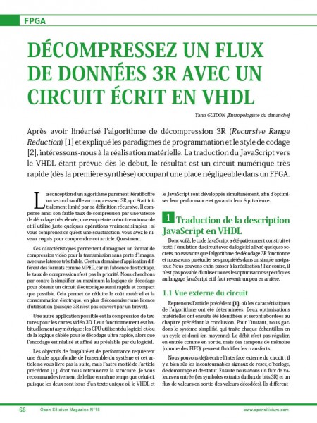
Another set of articles in OpenSilicium
01/02/2016 at 12:27 • 0 commentsPublication is progressing, with 2 articles about the coding style and the optimisation of the algorithm (using a linearisation of the recursive system).
16 pages at the end of OpenSilicium n°17 !
![]()
More to come, whenever I have time ;) -
Publication in Open Silicium
11/21/2015 at 01:31 • 0 commentsA first article is already available in Open Silicium n°16 (in french). It is pretty general and the explanation of the algorithm's subtleties will appear in january 2016 in Open Silicium n°17.
![]() Hopefully, the VHDL will be published in OS n°18 (april 2016 ?) (done: Another article about the VHDL implementation)
Hopefully, the VHDL will be published in OS n°18 (april 2016 ?) (done: Another article about the VHDL implementation) -
Color spaces
09/29/2015 at 20:47 • 0 commentsNote for later : Test a variety of lossless colorspace conversions and see which performs best :-)
- G, R-G, B-G
This one is the simplest !
; encoding
Y = G
Cb = B - G
Cr = R-G

; decoding
G = Y
B = Cb - Y
R = Cr - Y
Latency is 1 addition (1 cycle). 8-bits components wrap around on overflow.- Reversible Color Transform (RCT)
https://en.wikipedia.org/wiki/JPEG_2000#Color_components_transformation
; encoding
Y = ( R + 2G + B) >> 2
Cb = B - G
Cr = R - G
; decoding
G = Y - ((Cb + Cr)>>4)
R = Cr + G
B = Cb + G
That one is very nice, encoding takes 1 cycle and decoding 2 cycles. Is it more efficient than the previous one ?- YCoCg
It's a bit different https://software.intel.com/en-us/node/503873
; coding
Y = R/4 + G/2 + B/4
Co = R/2 - B/2
Cg = -R/4 + G/2 - B/4
; or better :
t = (R + B) >> 1
Co = (R - B) >> 1    ; I have to find an "add-sub" circuit, but A+B and A-B have the same LSB
Y = (G + t ) >> 1
Cg = (G - t) >> 1

; decoding
R = Y + Co - Cg
G = Y + Cg
B = Y - Co - Cg
Coding and decoding use 4 add or sub each but more bits are needed to preserve perfect reversibility.- YCoCG24
I love this one. I'm not sure who designed it first, it uses a different lifting scheme that preserves reversibility
; encoding
Co = B - R
R = R + Co>>1
Cg = R - G
Y = G + Cg>>1

; decoding
G = Y - Cg>>1
Cg = Cg + Y
R = Cg - Co>>1
Cg = Co + R
It is perfectly reversible at the price of a longer critical datapath.
Which of those transforms is the best in practice ?
20170529:
See the solution at colorspace decomposition
-
Simplicity
09/28/2015 at 16:28 • 0 commentsGoogle is releasing their incredible image compression algorithms, currently called Brotli, and proposes it as an Internet standard : http://www.ietf.org/id/draft-alakuijala-brotli
The 3R codec goes in the reverse direction : speed is important but compression ratio is not, I want the codec to be as small and simple as possible. No huge constant tables, hopefully a few hundreds of lines of source code, a thousand logic gates at most...
But it is well known that simplicity is complicated ! It is not a sophisticated design and I am interested only by the "low hanging fruits", the easy and cheap tricks that compress the most data.
-
Synthesis/place/route results
09/01/2015 at 13:23 • 0 commentsThanks to extensive simulations with GHDL, the VHDL source code synthesised "out of the box" and effortlessly reached 110MHz on the venerable ProASIC3 FPGA family. One SRAM block and about 450 tiles (LUT3) are used.
The SmartFusion2 has a different structure and also provides smaller, faster SRAM blocks. Only 120 LUT4 are used but I thought I'd reach more than the announced 147MHz... I'm believe I might shave a nanosecond or two if I read the doc well.
I still have to try with Xilinx (S3E, Artix) and Lattice (MachXO2 and ICE40) but I have no experience with them... That might be a good opportunity to try Antti's toys ;-)
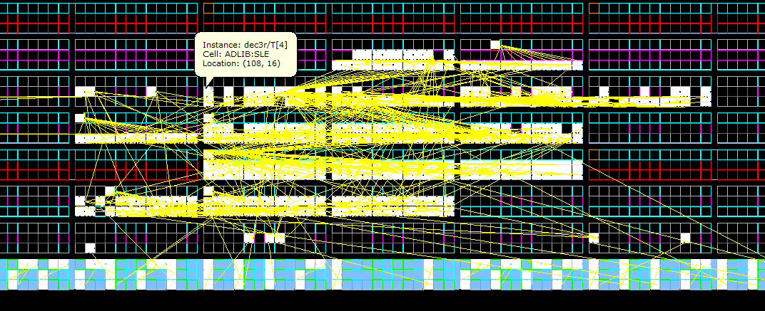
Here is a screenshot of the P&R's map for the SmartFusion2 target.
![]()
Recursive Range Reduction (3R) HW&SW CODEC
A high speed circuit design in JS and VHDL for decoding 3R bitstreams, a "quasi-entropy" code that compacts series of correlated numbers.
 Yann Guidon / YGDES
 The milestones have been finally reached but a lot of work remains before the sound and image compressors finally go live in FPGA.
 Hopefully, the VHDL will be published in OS n°18 (april 2016 ?) (done: